Do you have a question about the Thermann 16NG50-6 and is the answer not in the manual?
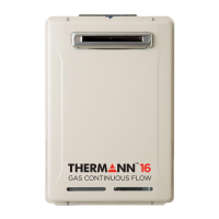
| Brand | Thermann |
|---|---|
| Model | 16NG50-6 |
| Category | Water Heater |
| Language | English |
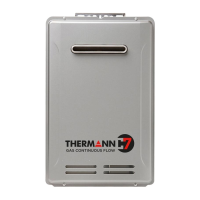
Unit is for outdoor installation only to prevent danger from oxygen deficiency and incomplete combustion.
Instructions for responding to gas leaks, including stopping use and closing the gas valve.
Verify the unit's gas type and power supply specifications match the label.
Details the unit's electric heaters for freeze prevention and the need for power supply.
Ensure adequate space around the unit for maintenance and service access.
Warning against touching power plugs with wet hands due to electric shock risk.
Ensure the power plug is clean, undamaged, and fully inserted.
Avoid pulling the power cord to remove the plug; prevent fire hazards.
Never use a bundled power cord to prevent heat generation and fire.
Damaged cords must be replaced by authorized personnel with specific parts.
Outlines installation requirements including regulations, standards, and gas authority notification.
Inspect unit for damage upon delivery and ensure it's correct for the gas supply.
Location of the data plate on the outside of the cabinet.
Information on identifying the gas type (Natural Gas or Propane) from the label.
Advise to carefully read warning labels located on the side of the cabinet.
Unit approved for outdoor installation only; clearance details must be followed.
Guidance on using a fixing method sufficient to support the unit's weight.
Connection details for cold water supply, including pipe size and unions.
Requirement for a gate or ball valve on the cold water inlet as per national plumbing code.
Information on installing one, two, or three remote control panels as optional extras.
Guidance on suitable locations for remote controllers in kitchens, laundry, bathrooms, and ensuites.
Instructions for installing wiring to the main unit and connecting it to terminals.