Do you have a question about the Thermo IEC Micromax 3590 and is the answer not in the manual?
Instructions for handling the unit upon delivery and retaining packaging.
Guidelines for placing the centrifuge, required clearance, and surface requirements.
Details on model voltage/frequency requirements and fuse specifications.
Procedure for safely moving the unit using suction cups.
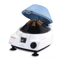
Overview of the control panel, buttons, and display functions.
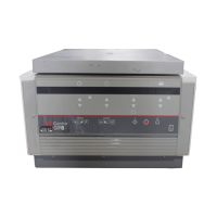
Explanation of the refrigeration system operation and limitations for RF models.
Step-by-step guide for initial setup and operation of the centrifuge.
Guidance on rotor installation, balancing, and proper placement.
Description of Timed Run, Hold Mode, and Momentary modes of operation.
Explanation of audible beeps and on-screen warning/error messages.
Information on chemical resistance of centrifuge materials.
Notes on minimizing sample heating during operation.
Table detailing rotor specifications, speeds, RCF, and radius.
Table showing material resistance to various chemicals.
Table detailing material compatibility with decontamination methods.
Procedures for cleaning the centrifuge and its components.
Procedure to bypass the lid interlock if power fails.
General troubleshooting steps for common unit failures.
List of available spare parts with catalog numbers.
Details on fuses that are not intended for user replacement.
Warranty terms and conditions for the centrifuge and rotors.
Requirements for returning equipment for service or repair.
Table summarizing model voltage, frequency, max speed, force, tubes, and volume.
Details on control functions and operational repeatability.
Important safety warnings and cautions for servicing the unit.
Information on any specialized tools required for service.
Guidance on diagnosing and resolving unit malfunctions.
Details on the cover assembly and strike adjustment.
Procedures for removing the rear and main cabinet sections.
Information on gaskets for lid liner and refrigeration models.
Details on the latch assembly, microswitch, and solenoid.
Overview of the power entry module and its components.
Troubleshooting procedures for AC power and fuses.
Overview of the display, logic, and power circuit boards.
Description of the brushless DC motor and its power drive system.
Identification and description of Power PCB LEDs and test points.
Procedures for replacing display and logic circuit boards.
Procedure for removing and replacing the power board.
Testing and replacement procedures for the drive motor.
Information on the speed sensor, its inspection, and replacement.
Explanation of the brake system operation and service.
General overview of the refrigerated Micromax capabilities and requirements.
Procedures for testing the compressor and condenser fan.
Procedure for testing the solid state relay for the compressor.
Procedure for verifying thermistor resistance at different temperatures.
Explanation of the pressure switch function and replacement.
List of included schematic and assembly drawings for various components.
| Brand | Thermo IEC |
|---|---|
| Model | Micromax 3590 |
| Category | Laboratory Equipment |
| Language | English |