2.3 Power Configuration
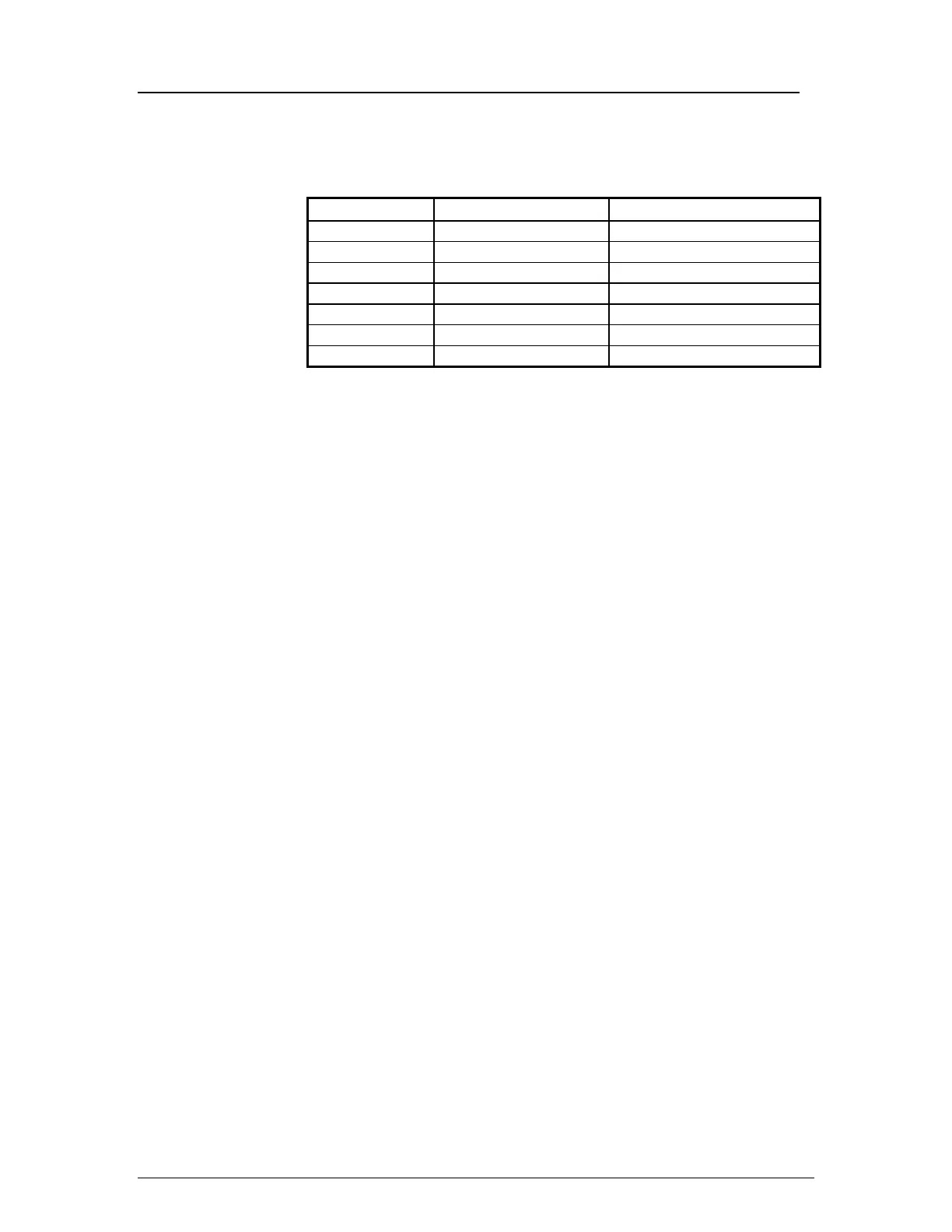
The Micromax model numbers, and voltage and frequency
requirements are listed in the table below.
MODEL VOLTAGE FREQUENCY
3590 120 60 Hz
3591 220 - 240 50/60 Hz
3592 (RF) 120 60 Hz
3593 (RF) 220 - 240 50 Hz
3594 (RF) 220,230 60 Hz
3595 100 50/60
3596 (RF) 100 50/60 Hz*
Ensure that your site is configured to match the
centrifuge's power requirements. Plugging the Micromax
into incorrect voltage or frequency will void your
warranty.
* Line Frequency Selection
(3596, Micromax RF)
Locate the 50/60 Hz selector switch to the left of the power
receptacle at the rear of the centrifuge. Adjust this switch
to match the line frequency at the site.
Fuses Fuses are located at the back of the unit.
To install fuses:
Locate the power entry module on the back side of the
unit. The removable fuse drawer is located in the
module. A small latch holds the drawer in place. Press
this latch, then slide the drawer out.
• Cat. No. 3590: The fuse drawer will have one spare
and one active fuse installed at the factory. Fuse is
rated for 6.25 Amps (part no. 50606B).
• Cat. No. 3591: The fuse drawer will have two active
fuses installed at the factory. Fuse is rated for 4.0
Amps (part no. 43689).
• Cat. No. 3592: The fuse drawer will have one spare
and one active fuse installed at the factory. Fuse is
rated for 8 Amps (part no. 50606A).
Micromax Series
3
Service Manual
 Loading...