Do you have a question about the Thermo King SL-400e and is the answer not in the manual?
Details high and low voltage hazards, capacitor safety, ESD precautions, and battery handling.
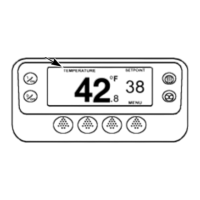
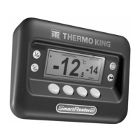
Describes the HMI Control Panel, its display, hard and soft keys, and operation.
Details the Base Controller's heart, mounting, hardware/software versions, and operation.
Lists and describes components like pressure transducers, solenoids, and ETV.
Covers essential features like temperature units, restart, setpoints, fuel saver, and door open settings.
Describes the OptiSet Plus Temperature Management System for tailored profiles.
Explains the HMI Control Panel's display, icons, hard keys, and soft keys.
Details the procedures for powering the unit on and off using the HMI.
Guides on how to adjust numerical and named product setpoints.
Details inserting, accessing, downloading, and flashing files via USB.
Explains how to view, clear, and interpret various alarm types.
Describes how to use test modes for diagnosing unit components and circuits.
Details how to access and change programmable features and settings.
Detailed troubleshooting for critical alarms related to sensors, engine, and circuits.
Covers alarms related to evaporator coil, return air, discharge air, ambient, coolant, and calibration.
Addresses alarms for coolant temperature, RPM sensor, oil pressure, and engine start failures.
Covers alarms for evaporator temperature, discharge pressure, cooling/heating cycles, and capacity.
Details alarms for alternator, electric motor, battery voltage, and electric heat circuits.
| Brand | Thermo King |
|---|---|
| Model | SL-400e |
| Category | Control Systems |
| Language | English |