Do you have a question about the Thermo King SR-2 SmartReefer2 and is the answer not in the manual?
Manual detailing diagnostic procedures for SR-2 Microprocessor Control System.
Specifies models the manual applies to: SB-110, SB-210, SB-310, SL-400e SR-2.
Identifies Microprocessor Software Revision B002 and HMI Control Panel Software Revision 6502/6503 or 6602/6603.
Explains the content and structure of the manual for easy information retrieval.
Contains essential safety information for microprocessor control systems before working on the unit.
Details the microprocessor control system hardware, components, and connectors.
Explains the operation of the control system software and programmable features.
Provides information on HMI control panel features and unit operation.
Guides technicians on identifying and repairing problems using alarm codes and symptoms.
Details functional tests, replacements, and setup procedures for SR-2 components.
Provides information on software features, hardware interchangeability, and bulletins.
Contains diagrams for SB and SL series units, including wiring and schematic views.
General safety guidelines for operating and servicing the unit.
Cautionary notes regarding automatic unit start and stop functions.
Guidelines for safe handling and environmental protection of refrigerants.
Precautions and first aid measures for high and low voltage electrical hazards.
Overview of the SR2 microprocessor controller as a self-contained temperature control unit.
Details the main components of the SR2 microprocessor control system.
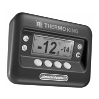
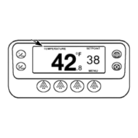
Description of the Human Machine Interface, including display and touch keys.
Location and function of the SR2 microprocessor and its interface board.
Information on interface board fuses, relays, and LED functions.
Explanation of various sensors used for monitoring system conditions.
Description of components used for sensing and controlling the refrigeration system.
Description of components used for sensing and controlling the diesel engine.
Details the three communication ports: CargoWatch, ServiceWatch, and Printer.
Features of the electric standby option for Model 50 units.
Explains how the software controls the refrigeration system and interfaces with the operator.
Describes the basic menu hierarchy: Temperature Watch, Main Menu, Maintenance Menu, Guarded Access Menu.
Details special operator functions available from the Standard Display.
Explains menus for technicians to view information and perform diagnostics.
Describes menus for configuring unit operation and programmable features.
Allows configuration of overall unit operation to end user requirements.
Temperature management system for defining and tailoring ten different temperature ranges.
Setup menu for CargoWatch datalogger, including sensor logging and naming.
Specifies the actual unit configuration parameters like engine and compressor type.
Details the HMI Control Panel, its display, keys, and communication.
Procedure for powering the unit on and off using the ON and OFF keys.
Describes the default display and the display mode after inactivity.
Procedure for adjusting the setpoint using the HMI control panel keys.
Describes automatic preheating and starting of the diesel engine.
Procedure for manually initiating a defrost cycle.
Procedure for selecting between Cycle Sentry and Continuous operating modes.
Procedure for accessing and viewing unit gauges.
Procedure for accessing and viewing unit temperature sensor readings.
Flowchart illustrating the navigation within the main menu.
Instructions for accessing and navigating submenus within the main menu.
Details options available in the main menu: Language, Alarms, Datalogger, Hourmeters, Mode, Pretrip, etc.
Explanation of different alarm types: Log, Check, Prevent, and Shutdown alarms.
Procedure for viewing, clearing, and obtaining help for active alarms.
Information on accessing and using the CargoWatch Data Logger.
Procedure for displaying and scrolling through unit hourmeters.
Selecting and managing unit operating modes like Cycle Sentry and Sleep Mode.
Steps for performing a Pretrip Test to verify unit operation.
Procedures for manually switching between diesel and electric modes.
Procedure for adjusting the HMI control panel display brightness.
Procedure for checking the unit's time and date settings.
Overview of functions available in the maintenance menu for technicians.
Steps to access and navigate the maintenance menu.
Procedure for forcing the unit into known modes for diagnostic purposes.
Procedure for energizing and de-energizing individual control devices for testing.
Technician tests for HMI control panel functionality (LCD, Keypad, etc.).
Procedure for system evacuation and charging with refrigerant.
Overview of menus for checking and changing unit's programmable features.
Procedure for accessing and navigating the Guarded Access Menu.
Guides technicians in identifying and repairing problems using alarm codes and symptoms.
Important procedures for working with SR-2 microprocessors.
Essential precautions to protect microprocessors and HMI control panels from ESD.
Provides corrective actions based on specific alarm codes encountered.
Categorizes alarms into Log, Check, Prevent, and Shutdown types.
Detailed troubleshooting for specific alarm codes, starting with '00 NO ALARMS EXIST'.
Troubleshooting guide for the evaporator coil sensor, including alarm conditions and diagnosis.
Troubleshooting guide for the control return air sensor, including alarm conditions and diagnosis.
Troubleshooting guide for the control discharge air sensor, including alarm conditions and diagnosis.
Troubleshooting guide for the ambient temperature sensor, including alarm conditions and diagnosis.
Troubleshooting guide for the coolant temperature sensor, including alarm conditions and diagnosis.
Troubleshooting guide for the engine RPM sensor, including alarm conditions and diagnosis.
Diagnosis for high evaporator temperature alarm, referencing other alarm codes.
Diagnosis for high discharge pressure alarm, including HPCO switch function.
Diagnosis for unit controlling on an alternate sensor due to primary sensor failure.
Diagnosis for sensor failure leading to unit shutdown or low speed operation.
General sensor check for erratic readings or inaccuracies.
Troubleshooting for the intake air heater circuit, including current draw checks.
Diagnosis for engine crank failure, including battery, starter, and fuse checks.
Diagnosis for high engine coolant temperature, including cooling system checks.
Diagnosis for low engine oil pressure, including switch and circuit checks.
Diagnosis for engine start failure, including fuel system and intake checks.
Check of cooling cycle operation, including temperature differential and refrigerant level.
Check of heating cycle operation, including temperature differential and refrigerant level.
Diagnosis for cooling cycle malfunction, including three-way valve and pilot solenoid checks.
Diagnosis for heating cycle malfunction, including three-way valve and pilot solenoid checks.
Procedure for checking alternator operation, belt, and connections.
Diagnosis for reduced refrigeration capacity, including superheat and airflow checks.
Procedure for handling Pretrip Test interruptions or failures.
Troubleshooting for the defrost damper circuit, including relay and solenoid checks.
Diagnosis for a stuck defrost damper, including current draw and binding checks.
Diagnosis for the oil pressure switch, including voltage and continuity checks.
Diagnosis for low refrigeration capacity, including refrigerant level and superheat checks.
Diagnosis for engine RPM issues, including speed adjustments and linkage checks.
Troubleshooting for the run relay circuit, including fuse, LED, and switch checks.
Diagnosis for electric motor failure, including contactor, overload, and alternator checks.
Diagnosis for engine coolant level issues, including sensor and switch checks.
Diagnosis for incorrect phase rotation of standby power or motor wiring.
Check of the water valve circuit (not implemented).
Troubleshooting for the high speed solenoid circuit, including relay and current checks.
Diagnosis for engine coolant temperature issues, including level and radiator checks.
Diagnosis for unit forced to low speed operation due to high engine temperature or discharge pressure.
Diagnosis for unit in low speed modulation due to high engine coolant temperature.
Diagnosis for fuel system issues, including fuel level and pressure checks.
Troubleshooting for the hot gas solenoid circuit, including LED and current checks.
Diagnosis for blocked air chute or restricted air flow.
Diagnosis for drive belt slippage indicated by RPM and alternator frequency ratio.
Procedure for resetting the HMI control panel clock/calendar after power interruption.
Troubleshooting for the pilot solenoid circuit, including LED and current checks.
Alarm indicating Service Test or Interface Board Test timed out.
Diagnosis for low battery voltage issues, including charging system and alternator checks.
Indicates shunt circuit is out of calibration during Pretrip Test.
Diagnosis for engine stoppage, including fuel level, fuses, and seized components checks.
Alarm indicating programmable hourmeter for Pretrip Reminder has expired.
Diagnosis for low engine oil level, including switch and harness checks.
Check of the liquid line solenoid circuit (not implemented).
Indicates an internal fault occurred in the microprocessor.
Alarm indicating hourmeter readings exceeded 499,999 hours.
Indicates programmable features reset to factory defaults, usually after a cold start.
Indicates too many events occurred during download or at once.
Check compressor temperature sensor (not implemented).
High compressor temperature alarm (not implemented).
High compressor temperature shutdown alarm (not implemented).
Low engine coolant temperature alarm (not implemented).
Secondary alarm indicating unit in temporary shutdown for restart attempts.
Indicates unit was forced into a different operating mode due to abnormal conditions.
Diagnosis for discharge pressure sensor, including voltage and continuity checks.
Diagnosis for suction pressure sensor, including voltage and continuity checks.
Diagnosis for ETV circuit, including pressure checks and refrigerant level.
Diagnosis for electric motor overload relay trip.
Diagnosis for electric ready input, checking standby power and phase detection.
Alarm indicating sensor grades are not properly set in the Guarded Access Menu.
Low compressor suction pressure alarm (not implemented).
Check loader #1 circuit (not implemented).
Check loader #2 circuit (not implemented).
Diagnosis for low fuel level, including fuel sensor harness check.
Diagnosis for fuel level sensor, including harness and sensor replacement.
High compressor pressure ratio alarm (not implemented).
Diagnosis for door open timeout, checking door switch operation.
Diagnosis for unit configuration mismatch, verifying and setting configuration.
Check electric heat circuit (pretrip test only).
Check high pressure cut out switch (not implemented).
Check high pressure cut in switch (not implemented).
Alarm indicating automatic switch from diesel to electric operation.
Alarm indicating automatic switch from electric to diesel operation.
Check PWM/liquid injection circuit (pretrip test only).
Check diesel/electric relay operation and current draw.
Alarm indicating setpoint change was not confirmed.
Alarms for engine, electric, and total unit run time maintenance reminders.
Check spare digital inputs (pretrip only).
Check spare digital outputs (pretrip only).
Diagnosis for damper motor heater output, related to defrost damper status.
Troubleshooting for the display return air sensor, including dual sensor issues.
Troubleshooting for the display discharge air sensor, including dual sensor issues.
Index of all SR-2 service procedures with their corresponding page numbers.
Procedure to confirm proper operation of the microprocessor and interface board.
Procedure to confirm proper operation of the HMI Control Panel.
Procedure to confirm HMI Control Panel operation using built-in display self-tests.
Procedure to retrieve and record current microprocessor settings before replacement or cold start.
Procedure for replacing the microprocessor or interface board assembly.
Procedure for replacing the HMI Control Panel assembly.
Procedure to program sensor grades and programmable features to customer specifications.
Procedure to perform a Cold Start on the microprocessor.
Procedure to calibrate sensor grades of replacement Return Air and Discharge Air sensors.
Procedures to prevent microprocessor damage during welding operations.
Procedure to set fixed running time hourmeters after microprocessor replacement.
Procedure to update SR-2 microprocessor software using a computer and Wintrac.
Procedure to change or update SR-2 HMI Control Panel software using Wintrac.
Information on phase detect module operation, connections, and diagnostic procedures.
Instructions for understanding, using, and diagnosing the CargoWatch Data Logger.
Information on understanding and using the ServiceWatch Data Logger.
Procedure to confirm proper operation of unit temperature sensors.
Procedure to confirm proper operation of suction or discharge pressure sensors.
Procedure to test and replace the oil level switch.
Procedure to test the oil pressure switch for proper operation.
Procedure to confirm proper operation of the optical coolant level sensor.
Procedure to confirm proper operation of the magnetic coolant level sensor.
Procedure to test the coolant temperature sensor for proper operation.
Procedure to test and adjust the RPM sensor.
Procedure to check the operation of the electronic throttling valve.
Correct procedures for checking harness continuity on solid state devices.
Details SR-2 microprocessor and HMI software revisions and interchangeability.
Information on SR-2 hardware features, where used, and interchangeability.
Compares Economy Mode settings to Standard Mode defaults for Cycle Sentry and Continuous modes.
Lists NAD and ESA service and warranty bulletins applicable to SR-2 controllers.
Schematic diagram for SB series units with Yanmar engines (NAD Manuals Only).
Wiring diagram for SB series units with Yanmar engines (NAD Manuals Only).
Schematic diagram for SL-400e units (ESA Manuals Only).
Section for providing feedback and comments on the manual for improvement.
| Alerts | Audible and visual alarms |
|---|---|
| Refrigerant | R-452A |
| Power Supply | DC |
| Power Source | Vehicle Battery |
| Connectivity | cellular |
| Control Modes | Continuous, Start/Stop |
| Display Type | LCD |
| Data Logging | Yes |
| Compatibility | Thermo King refrigeration units |
| Operating Temperature Range | -40°C to +55°C (-40°F to +131°F) |