Do you have a question about the Thermo King Super II SR+ and is the answer not in the manual?
Details of the Thermo King X430 compressor used in the unit.
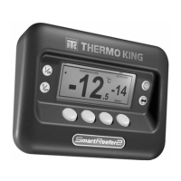
Features and functions of the THERMOGUARD uP IV+ microprocessor controller.
Explanation of the CYCLE-SENTRY fuel-saving start-stop system.
How the optional modulation system provides precise temperature control.
Step-by-step process of unit startup and operation.
Overview of different operational modes available for the unit.
Details on how modulation is enabled, disabled, and its operating range.
Explanation of the defrost mode initiation and termination conditions.
Technical specifications for the SE 2.2 diesel engine, including fuel, oil, and performance data.
Specifications for belt tensioning using the TK Gauge.
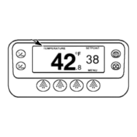
Description of the two control sets: switch panel and microprocessor panel.
Functions of switches on the control panel for basic unit operation.
Procedure for using the switch to preheat and start the diesel engine.
How to initiate a manual defrost cycle if required.
The function of the air switch in initiating automatic defrost cycles.
Selecting between CYCLE-SENTRY and CONTINUOUS operating modes.
Steps for pre-cooling the trailer and unit before loading.
Guidelines for loading product into the trailer for optimal temperature control.
Steps to follow after loading product to ensure proper operation.
Routine checks to perform after completing a trip.
Overview of the control panel, including display, keypad, and switch panel.
Detailed explanation of the switches on the control panel.
Functionality of the main On-Off switch for unit operation.
Operation of the Preheat-Start switch for engine ignition.
Procedure for manually initiating a defrost cycle.
Selecting between CYCLE-SENTRY and CONTINUOUS modes.
How to interpret the LCD display and its icons.
General principles of unit operation with the microprocessor.
Step-by-step guide for manually starting the unit.
How the unit automatically starts in CYCLE-SENTRY mode.
Description of key instruments like ammeter and display.
Explanation of various fuses, links, and cutout switches for safety.
Essential checks before starting the unit for operation.
Detailed steps for manually starting the unit.
Procedure for conducting a full pre-trip test of the unit.
How to view the unit's software revision number.
Instructions for entering and using the service test mode.
Important considerations and cautions for using service test mode.
Definitions of various test modes available for diagnostics.
Explanation of the functions of each key on the microprocessor keypad.
How to navigate and view different data screens.
Understanding the standard display of return air temperature and setpoint.
Steps to adjust the temperature setpoint using the keypad.
How to switch between CYCLE-SENTRY and CONTINUOUS operating modes.
How to view specific data screens using the SELECT key.
How to lock the display screen to view specific data.
Procedure for starting the diesel engine manually or automatically.
How to manually initiate a defrost cycle.
How to view, understand, and clear alarm codes.
List of alarm codes associated with software revision 04XX.
Diagnostic procedures for the Australian Bosch alternator.
Steps to diagnose and test the unit's charging system.
Procedure to test alternator field windings, brushes, and slip rings.
Maintenance and inspection guidelines for the unit's battery.
Explanation of charging system operation and troubleshooting.
Function and testing of glow plugs for engine starting.
Identification and purpose of various fuses protecting the electrical system.
Function and testing of the low oil pressure safety switch.
Overview of the defrost system and its components.
Steps to verify the correct operation of the defrost cycle.
How to test and adjust the air switch for defrost initiation.
Testing and function of the engine oil level switch.
Methods for testing various temperature and pressure sensors.
Procedures for replacing air, coil, and temperature sensors.
Detailed explanation of the engine's oil circulation and lubrication system.
Procedure for changing the engine oil and filter.
Description of the engine's cooling system and its components.
Guidelines for maintaining the engine's antifreeze mixture.
Step-by-step instructions for draining and replacing antifreeze.
Procedure to remove trapped air from the cooling system.
Steps for adjusting engine valve clearance for optimal performance.
Information on the recommended engine thermostat for operation.
Overview of the diesel engine's fuel system components and operation.
Procedure to remove air from the fuel system.
Function and maintenance of the water separator and fuel filter.
Procedures for adjusting engine speeds (high and low).
Instructions for removing, installing, and timing the injection pump.
Function of the crankcase breather system.
Importance of the air cleaner and its restriction indicator.
Inspection and tensioning of engine belts.
Steps for replacing the fan belt.
Procedures for testing refrigerant charge in loaded and empty trailers.
How to interpret the sight glass for refrigerant moisture content.
Methods for detecting and testing for refrigerant leaks.
Procedures for checking compressor oil level under different ambient temperatures.
Testing and function of the high pressure cutout switch.
Function and checking procedure for the three-way valve.
Operation and control of the modulation valve.
Steps to test the modulation valve's function.
Function and testing of the hot gas solenoid valve.
Explanation of the Thermax-V system and its operation.
Removal and installation procedures for the pilot solenoid.
Removal and installation of the HPCO switch.
Removal and installation of the high pressure relief valve.
Removal and installation procedures for the throttling valve.
Steps for removing and installing the condenser coil.
Removal and installation of the discharge vibrasorber.
Replacement procedure for the in-line condenser check valve.
Removal and installation of the bypass check valve.
Procedures for removing and installing the receiver tank.
Removal and installation of the filter drier.
Steps for removing and installing the expansion valve assembly.
Repair procedure for the liquid line check valve.
Removal and installation of the Thermax-V expansion valve.
Torque specifications for unit and engine mounting bolts.
Guidelines for inspecting the unit for damage or loose parts.
Maintenance checks for the unit's coils.
Cleaning procedures for defrost drains to ensure they remain open.
Inspection of the defrost damper for wear and proper sealing.
Removal and installation procedures for the fan module.
Detailed steps for assembling the fan module.
Information on the fan shaft assembly and its maintenance.
Correct procedure for positioning the condenser fan on the shaft.
Steps for aligning the evaporator blower assembly for proper airflow.
Explanation of symbols and codes used in fault indication.
Table of alarm codes, possible causes, and test procedures.
Diagnosis and remedy for microprocessor power-up reset issues.
Troubleshooting for evaporator coil sensor faults.
Diagnosis and remedy for return air sensor issues.
Troubleshooting for engine water temperature sensor faults.
Diagnosis for engine failure to crank in CYCLE-SENTRY mode.
Troubleshooting steps for cooling cycle performance issues.
Diagnosis for pre-trip test abort conditions.
Diagnosis and remedy for low engine oil level conditions.
Troubleshooting steps for a blank or unlit LCD screen.
Diagnosis for when the engine fails to crank despite power.
Troubleshooting steps when the starter motor operates but the engine doesn't crank.
Common causes and remedies for engine failure to start after cranking.
Troubleshooting for issues causing the engine to stop shortly after starting.
Diagnosis for engine performance issues leading to reduced power.
Causes and remedies for excessive engine speed.
Troubleshooting steps when the engine does not shut off.
Diagnosis and remedies for engine knocking sounds.
Causes and solutions for engine overheating.
Troubleshooting for low or fluctuating engine oil pressure.
Diagnosis and remedies for excessive engine oil consumption.
Troubleshooting for battery charging system faults.
Troubleshooting rapid cycling between cooling and heating modes.
Diagnosis for unit cooling behavior during heat/defrost cycles.
Diagram and explanation of the refrigeration cycle without modulation.
Diagram and explanation of the refrigeration cycle with modulation.
Refrigeration diagram for defrost/heating without modulation.
Refrigeration diagram for defrost/heating with modulation.
| Brand | Thermo King |
|---|---|
| Model | Super II SR+ |
| Category | Control Systems |
| Language | English |