EasyManua.ls Logo

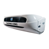
Thermo King RD-II MAX User Manual

Thermo King RD-II MAX
186 pages
To Next Page IconTo Next Page
Page #1 background imageLoading...
Page #1 background image
RD-II MAX
w/TK 3.95
TK 41023-1-MM (Rev. 1, 10/03)
Copyright© 2000 Thermo King Corp., Minneapolis, MN, USA.
Printed in USA.

Table of Contents

Question and Answer IconNeed help?

Do you have a question about the Thermo King RD-II MAX and is the answer not in the manual?

Thermo King RD-II MAX Specifications

General IconGeneral
BrandThermo King
ModelRD-II MAX
CategoryRefrigerator
LanguageEnglish

Summary

Safety Precautions

General Practices

Provides essential safety guidelines for operating and maintaining the unit.

Refrigerant Safety

Details hazards associated with refrigerant exposure and handling.

First Aid Measures

Outlines immediate first aid steps for common workplace injuries.

Refrigeration Oil Safety

Specifies precautions for handling and working with refrigeration oil.

Electrical Hazards

Highlights risks associated with electrical components and systems.

High Voltage Precautions

Details critical safety measures for working with high voltage circuits.

Low Voltage Precautions

Explains safety considerations for low voltage electrical circuits.

Specifications

Engine—TK 3.95 Specifications

Provides detailed technical specifications for the TK 3.95 engine.

Refrigeration System Specifications

Lists specifications for R-134a and R-404A refrigeration systems.

Engine Clutch Specifications

Details the engagement and torque specifications for the engine clutch.

Air Switch and Belt Tension

Specifies settings for the air switch and belt tension guidelines.

Electrical System Specifications

Details voltage, regulator settings, and capacitor specifications.

Thermostat and Motor Specs

Provides specifications for the thermostat and standby motors.

Standby Power Requirements

Outlines required circuit breakers and extension cord sizes.

Maintenance Inspection Schedule

Microprocessor and Engine Checks

Details inspection and service items for microprocessor and engine systems.

Electrical and Refrigeration Checks

Lists inspection points for electrical and refrigeration system components.

Structural Checks

Covers visual inspection of structural parts and connections.

Unit Description

General Unit Overview

Provides a general description of the RD-II MAX unit and its features.

Compressor and Controller Details

Describes the X426 compressor and TG-V microprocessor controller.

Operating Modes and Engine Operation

Explains the different operating modes and engine functions.

Defrost Operation and Unit Features

Details defrost operation, serial number locations, and unit features.

Unit Options and Protection Devices

Lists available unit options and protection devices for safe operation.

Operating Instructions

Unit Controls Overview

Introduces the main control box and its basic functions.

TG-V Controller Functions

Explains the operation and features of the TG-V microprocessor controller.

Remote Control Options

Describes the functions of optional remote control boxes.

Unit Indicators and Operation Modes

Details unit indicators, operating modes, and CYCLE-SENTRY operation.

Startup Procedures

Provides step-by-step instructions for starting the unit.

Loading and Post-Trip Procedures

Outlines procedures for loading cargo and post-trip checks.

Electronic Controls

TG-V Thermostat and Controller

Details the features and operation of the TG-V thermostat and controller.

Display Symbols and Control Keys

Explains the meaning of display symbols and the function of control keys.

General Display and Data Display

Describes general display information and how to view operating data.

Setpoint Entry and Alarm Codes

Provides instructions for entering setpoints and managing alarm codes.

Guarded Access and Setup Codes

Explains guarded access mode and how to change setup codes.

Terminal Identification and Testing

Identifies TG-V terminals and provides sensor and module testing procedures.

Electrical Maintenance

Alternator and Charging System

Covers alternator testing, voltage output, and battery maintenance.

Glow Plugs and RPM Sensor

Details testing procedures for glow plugs and the RPM sensor.

Engine Reset and Oil Pressure Switches

Explains the function and testing of engine reset and oil pressure switches.

Defrost Air Switch and Heating System

Covers defrost air switch adjustment and TherMax heating system.

In-Cab Controller and Connector Pins

Provides field test procedures and connector pinouts for the in-cab controller.

Engine Maintenance

Engine Lubrication System

Describes the engine's oil pressure system and lubrication flow.

Engine Oil and Filter Maintenance

Details procedures for engine oil changes and oil filter replacement.

Engine Air Cleaner Service

Covers maintenance for both oil bath and dry type air cleaners.

Engine Cooling System

Explains the cooling system operation and antifreeze maintenance.

Engine Fuel System

Details the fuel system components and troubleshooting.

Fuel Filter and Electric Fuel Pump

Covers fuel filter replacement and electric fuel pump operation.

Fuel Solenoid System and Adjustments

Explains the fuel solenoid system, timer, and troubleshooting.

Injection Pump Service

Details procedures for injection pump removal, installation, and timing.

Engine Valve Clearance and Belts

Covers valve clearance adjustment and belt inspection/tension.

Refrigeration Maintenance

Evacuation Procedures

Explains the importance and steps for system evacuation.

Refrigerant Leaks and Unit Charging

Covers leak detection and the process of charging the system.

Refrigerant Charge Testing

Describes methods for testing refrigerant charge levels.

Compressor Oil and High Pressure Cutout

Covers checking compressor oil and the function of the HPCO switch.

Refrigeration Service Operations

Unit Commissioning and Pump Down

Details unit commissioning and low side pump down procedures.

Accumulator and Compressor Service

Covers removal and installation procedures for the accumulator and compressor.

Component Service: Valves, Coils, Driers

Describes service procedures for check valves, coils, and dehydrators.

Three-Way Valve Repair and Recommendations

Covers three-way valve repair and R-404A equipment recommendations.

Hilliard Clutch Maintenance

Centrifugal Clutch Change Procedure

Details the process for changing the large truck unit centrifugal clutch.

Clutch Maintenance and Tools

Covers inspection requirements, necessary tools, and grease.

Disassembly and Assembly Procedures

Provides step-by-step instructions for clutch disassembly and assembly.

Structural Maintenance

Mounting Bolts and Lift Points

Details torque specifications for mounting bolts and notes lift points.

Unit Inspection and Coil Cleaning

Covers unit inspection and cleaning of evaporator/condenser coils.

Defrost Damper and Jackshaft Assembly

Describes defrost damper adjustment and jackshaft assembly maintenance.

Fanshaft Assembly Service

Covers disassembly and reassembly procedures for the fanshaft assembly.

Mechanical Diagnosis

Unit Switch and Engine Cranking Issues

Troubleshoots issues when the unit switch is on but the engine won't crank.

Engine Start and Power Issues

Diagnoses problems with engine starting and reaching full power.

Smoke, Noise, and Temperature Issues

Addresses excessive smoke, engine knocks, and overheating problems.

Oil Pressure and Consumption Issues

Troubleshoots low oil pressure, high oil consumption, and blue smoke.

White Smoke and Battery Recharging

Diagnoses white smoke (fuel issues) and battery recharging problems.

CYCLE-SENTRY Diagnosis

Relay and Starter Troubleshooting

Diagnoses issues with run relays, preheat relays, and starters.

Unit Start/Stop and Mode Troubleshooting

Addresses problems with automatic start/stop, modes, and temperature sensing.

Electric Standby (Optional) Diagnosis

Power and Motor Operation Issues

Troubleshoots indicator lights, motor not running, and contact chatter.

Heater and Battery Charging Issues

Diagnoses electric heater and battery charging problems.

Refrigeration Diagnosis

Symptom-Based Refrigeration Diagnosis

Provides a chart correlating symptoms to possible causes in refrigeration systems.

Refrigeration Diagrams

Cool Cycle Diagram

Illustrates the refrigerant flow during the cool cycle operation.

Condenser Evacuation Cycle Diagram

Shows the refrigerant path during condenser evacuation.

Heat and Defrost Cycle Diagram

Illustrates the refrigerant flow during heat and defrost cycles.

Related product manuals