Do you have a question about the Thermo King Rail Edition SLXi-DRC and is the answer not in the manual?
Details changes made to the manual over time.
Provides context, disclaimers, and references for the manual.
Explains procedures for safely recovering refrigerant, emphasizing environmental protection.
Defines DANGER, WARNING, CAUTION, and NOTICE symbols used in the manual.
Highlights key safety warnings and general practices for unit operation.
Provides specific safety guidelines for battery installation, routing, and removal.
Details hazards associated with refrigerants and oils, including PPE requirements.
Outlines electrical safety precautions, including low voltage and live components.
Provides precautions for servicing microprocessors and welding to prevent damage.
Details first aid measures for refrigerant, oil, coolant, battery acid, electrical shock, and asphyxiation.
Lists detailed specifications for the unit's diesel engine, including model, capacity, and performance.
Details belt tension settings and measurement methods for various belts.
Provides specifications for the refrigeration system components like refrigerant charge and oil type.
Lists specifications for the unit's voltage, battery, and charging system.
Lists current draw and resistance values for various electrical components.
Lists inspection and service tasks for the microprocessor based on operating hours.
Details routine engine checks and services required at different intervals.
Outlines inspection and service tasks for the refrigeration system.
Lists inspection and service tasks related to the unit's structure and components.
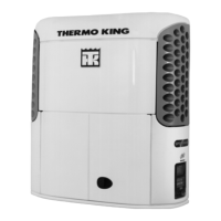
Provides a general description of the SLXi-DRC unit and its main features.
Highlights key design elements and technologies incorporated into the unit.
Describes the TK486V25X diesel engine used in the unit.
Details the Thermo King X430P compressor and the Electronic Throttling Valve.
Explains the functions and operation of the SMART REEFER 3 control system.
Describes the CYCLE-SENTRY start-stop system for fuel saving.
Explains the ServiceWatch and CargoWatch data logging capabilities.
Describes wireless communication and sensor system features.
Details OptiSet Plus and FreshSet for customized unit operation and temperature control.
Explains the unit's operating modes, sequence, and defrost cycles.
Identifies and describes key components located in the engine compartment.
Details various devices that protect the unit from operational faults and damage.
Indicates the locations for finding unit, engine, and compressor serial numbers.
Details the information found on the unit's laminated serial number plate.
Provides steps for diagnosing alternator issues, including identification and general info.
Explains the function and use of Fuse F4 in the base controller for alternators.
Specifies recommended test equipment for voltage and amperage measurements.
Details procedures for testing alternator output under load and general diagnostic evaluations.
Describes quick checks for alternator diodes and field current testing.
Covers inspection, maintenance, and load testing for filler cap and maintenance-free batteries.
Details the purpose and location of various fuses on the base controller, including Fuse F10.
Explains Smart FET outputs, LED functions, and information on the SR-3 microprocessor controller.
Describes the function and location of the fuse link for system protection.
Covers air heater testing and general inspection of unit wiring and harness routing.
Details the components and extended intervals of the EMI 3000 maintenance package.
Provides procedures for changing engine oil and oil filters, including capacity and type.
Explains potential causes and diagnostic steps for low engine oil pressure.
Describes the pressurized cooling system, its components, and antifreeze benefits.
Covers ELC recommendations, antifreeze maintenance, and procedures for checking and changing antifreeze.
Provides a procedure for bleeding trapped air from the engine cooling system.
Details the engine thermostat and procedures for testing the coolant level switch.
Describes how to check the float and replace the coolant level switch.
Covers operation, fuel line routing, and maintenance of the fuel system components.
Details field-serviceable procedures for the fuel system, including bleeding and maintenance.
Provides a step-by-step procedure for replacing fuel return lines.
Explains the process for bleeding air from the fuel system.
Details the procedure for draining water from the fuel tank to prevent damage.
Covers inspection and cleaning of the fuel pre-strainer.
Details the replacement of the fuel filter/water separator.
Provides procedures for adjusting high and low engine speeds.
Guides on how to correctly time the injection pump for optimal performance.
Provides examples and guidance for setting injection pump timing marks.
Explains how to align injection pump timing marks using stickers and gear alignment.
Details the steps for safely removing the injection pump from the engine.
Provides instructions for reinstalling the injection pump, including timing.
Describes the function and operation of the fuel solenoid on the injection pump.
Outlines the procedure for testing the fuel solenoid's electrical and mechanical operation.
Provides steps for replacing the fuel solenoid.
Describes the trochoid feed pump, its pressure, and potential leaks.
Details the procedure for replacing the trochoid feed pump.
Explains how to check and replace the cold start device for cold weather starting.
Provides detailed steps for adjusting engine valve clearances.
Describes the crankcase breather system and its function.
Covers the replacement interval and procedure for the EMI 3000 air cleaner.
Details belt inspection for wear and tension checking methods.
Provides a step-by-step guide for replacing the fan drive belt.
Continues the procedure for fan drive belt replacement, focusing on installation and alignment.
Explains how to adjust fan drive belt tension using pulley position and frequency gauge.
Describes the engine/cross shaft belt and its critical alignment and tensioning requirements.
Covers the assembly of the tensioner clutch and replacement of the engine/cross shaft belt.
Continues the belt replacement procedure with detailed steps for tensioning and alignment.
Details how to adjust the water pump belt tension using pulley sheaves.
Explains methods for testing refrigerant charge levels in empty and loaded trailers.
Details the steps to identify an excessive refrigerant charge in the system.
Describes the moisture indicator and how to detect refrigerant leaks.
Provides procedures for checking compressor oil levels under different ambient temperatures.
Explains how to test the HPCO switch for proper operation.
Describes the function and operation of the three-way valve bypass check valve.
Details the operation, testing, and control of the Electronic Throttling Valve.
Covers pressure transducer function and the operation of the hot gas bypass valve.
Illustrates and lists the various components of the refrigeration system.
Provides detailed procedures for removing and installing the compressor.
Details the process for removing the compressor coupling using specialized tools.
Provides instructions for installing the compressor coupling, emphasizing correct fitment.
Identifies compressors with pressurized seal cavities and related components.
Guides on replacing the hex drive compressor seal, including part preparation and installation.
Covers procedures for removing and installing the condenser coil, including cleaning recommendations.
Details the removal and installation of the discharge vibrasorber.
Explains the procedure for replacing the in-line condenser check valve.
Details the removal and installation of the bypass check valve.
Covers the removal and installation procedures for the receiver tank.
Provides procedures for removing and installing the filter-drier.
Details the removal and installation of the expansion valve assembly.
Covers the procedure for removing the heat exchanger.
Covers the procedure for installing the heat exchanger.
Details the removal and installation of the evaporator coil assembly.
Provides procedures for removing and installing the accumulator.
Guides on repairing the three-way valve, including disassembly and part inspection.
Covers checks for valve bleed hole diameter, piston bleed orifice, and check valve piston.
Details checking the seat orifice and the assembly/installation of the three-way valve.
Provides repair procedures for the bypass check valve.
Details the removal and installation of the pilot solenoid.
Covers the removal and installation of the suction vibrasorber.
Continues service procedures for the suction vibrasorber.
Details the removal and installation of the HPCO switch.
Provides procedures for removing and installing the high pressure relief valve.
Covers removal and installation of discharge and suction pressure transducers.
Details the procedure for removing the ETV stepper motor and piston assembly.
Guides on installing the ETV service kit, including O-ring lubrication and alignment.
Provides instructions for installing a complete ETV assembly.
Covers removal and installation of the hot gas bypass valve.
Details the procedure for replacing the internal oil filter in compressors.
Continues the procedure for internal oil filter replacement.
Explains how to check compressor oil pressure by calculating net oil pressure.
Completes the procedure for checking compressor oil pressure and troubleshooting low pressure.
Specifies torque values for unit and engine mounting bolts.
Outlines inspection points for loose wires, hardware, leaks, and physical damage.
Provides guidance on cleaning condenser, evaporator, and radiator coils, including intervals and methods.
Continues coil cleaning guidance, including specific methods and warnings.
Covers cleaning defrost drains and general unit installation considerations.
Describes the function and operation of the defrost damper.
Explains how to test the defrost damper and troubleshoot common alarm codes.
Provides the procedure for replacing the damper gear motor.
Covers fan locations and alignment procedures for condenser inlet orifices.
Details the procedure for aligning the evaporator fan blower.
Covers fan location and the initial steps for removing the fan shaft assembly.
Provides steps for disassembling the fan shaft assembly, including bearing removal.
Details the reassembly process for the fan shaft assembly, including bearing and housing preparation.
Covers the installation of the fan shaft assembly, blower, and related components.
Details removal and disassembly of the lower condenser blower assembly.
Covers reassembly and installation of the lower condenser blower assembly.
Details removal and disassembly of the cross shaft assembly.
Covers reassembly and installation of the cross shaft assembly.
Details the disassembly procedure for idler assemblies.
Covers reassembly and installation of idler assemblies.
Diagnoses common causes and remedies for engine not cranking or failing to start.
Diagnoses causes for low power, high speed, stopping issues, knocking, overheating, and low oil pressure.
Addresses high oil consumption and diagnosis of excessive engine smoke (white, black, blue).
Provides a matrix correlating refrigeration symptoms with possible causes.
Continues the matrix correlating refrigeration symptoms with possible causes.
Illustrates the refrigerant flow during the cool cycle.
Illustrates the refrigerant flow during heat and defrost cycles.
| Brand | Thermo King |
|---|---|
| Model | Rail Edition SLXi-DRC |
| Category | Refrigerator |
| Language | English |
