Do you have a question about the Thermo King E-200 and is the answer not in the manual?
Contacting Thermo King for breakdown and repair assistance with required information.
How to contact a local dealer for general inquiries and unit maintenance.
Providing feedback to improve manuals via an online survey.
Understanding DANGER, WARNING, CAUTION, and NOTICE symbols for safety.
Essential safety practices for operating the unit, including PPE and handling hot surfaces.
Safety for battery installation, cable routing, and automatic start/stop functions.
Safety guidelines for handling refrigerants and potential hazards.
Safety for refrigerant oil and first aid for chemical/physical exposures.
Explaining safety decals and their meanings for unit operation.
Safety precautions for unit operation, high voltage systems, and fans.
Warnings related to fan operations and remote start functions.
Information on refrigerant types and F-Gas decal indications.
Details on UNECE R10 decal samples for unit certification.
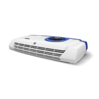
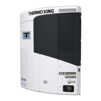
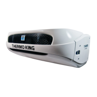
Description of E-Series units, including E-200 and E-200 MAX models.
Details on standard unit features and available optional enhancements.
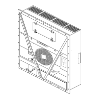
Detailed breakdown of the main system components like compressor, condenser, and evaporator.
Explanation of the electronic control module, HMI, and its characteristics.
Guide to the in-cab control panel, its keys, and display symbols.
Information on operating the unit in standby mode.
Details on the unit's electrical system, power sources, and fuse types.
Information on ignition power fuses and unit component fuses.
Explanation of the unit's operational modes: Cool, Heat, Null, and Defrost.
Procedures for starting the unit in engine operation and electric standby mode.
Understanding the standard display and examples for single/multi-temperature units.
Steps for setting and adjusting the desired temperature for single and multi-temp units.
How to select and manage compartment temperatures in multi-temperature units.
Steps to initiate and manage a manual defrost cycle for the evaporator.
Operating TK batteries, shorepower, and road mode statuses.
Understanding unit operation and status messages in road mode.
Procedures for activating and operating the unit in TK Hold-Over Mode.
Explanation of different alarm categories and buzzer functions.
Detailed descriptions and color codes for various alarm codes.
Procedures for resolving alarm conditions and clearing alarm codes.
Accessing and interpreting main menu and hourmeter information screens.
Performing thermostat checks, pre-cooling, and defrost before loading.
Guidelines for loading product to minimize frost and ensure air circulation.
Post-load checks including door closure and temperature adjustment.
Routine checks performed after the unit has completed a trip.
Technical specifications for the refrigeration system and compressor.
Specifications for fuses and the electrical control system.
Details on voltage, current, power, and RPM for fan motors.
Specifications for the compressor driver module and smart charger.
Reference to the official Thermo King warranty document.
List of checks to perform before each trip for operational readiness.
Detailed inspection procedures to be completed before unit operation.
Guidance on recommended inspection and service intervals based on usage.
Importance of preventative maintenance and adherence to schedules for unit longevity.
Locating serial numbers on the condenser, compressor, and smart charger module.
Thermo King's commitment to refrigerant recovery and regulatory compliance.
| Model | E-200 |
|---|---|
| Power Source | Electric |
| Refrigerant | R-452A |
| Weight | Condenser: 23 kg; Evaporator: 11 kg |
| Dimensions | Condenser: 741 x 563 x 211 mm; Evaporator: 698 x 530 x 174 mm |
| Cooling Capacity | 2000 W |
| Voltage | 12V / 24V DC |
| Refrigeration Capacity | 2000 W |
| Power Supply | 12V / 24V DC |