Engine Maintenance
105
10. Test the hold-in coil.
a. Energize the hold-in coil by placing a
jumper between the red wire (8D—pin A)
in the fuel solenoid connector and the 2
terminal at the control circuit.
b. Momentarily energize the pull-in coil by
placing a jumper between the white wire
(8DP—pin B) in the fuel solenoid
connector and the 2 terminal at the control
circuit. The fuel solenoid should make a
definite click when the pull-in coil is
energized, but should not click when the
pull-in coil is de-energized.
c. De-energize the hold-in coil by removing
the jumper from the red wire (8D—pin A)
and the 2 terminal. The fuel solenoid
should make a definite click when the
hold-in coil is de-energized.
d. If the hold-in coil does not function
properly, check the resistance of the
hold-in coil by placing an ohmmeter
between the red wire (8D—pin A) and the
black wire (CH—pin C) in the fuel
solenoid connector. The resistance of the
hold-in coil should be 11 to 13 ohms. If the
resistance of the hold-in coil is not in this
range, replace the fuel solenoid.
e. If the hold-in coil does function properly,
go to step 11.
11. Reconnect the fuel solenoid connector and the
main wire harness connector.
12. Remove the fuel solenoid relay from its socket
and make sure the On/Off switch is in the On
position.
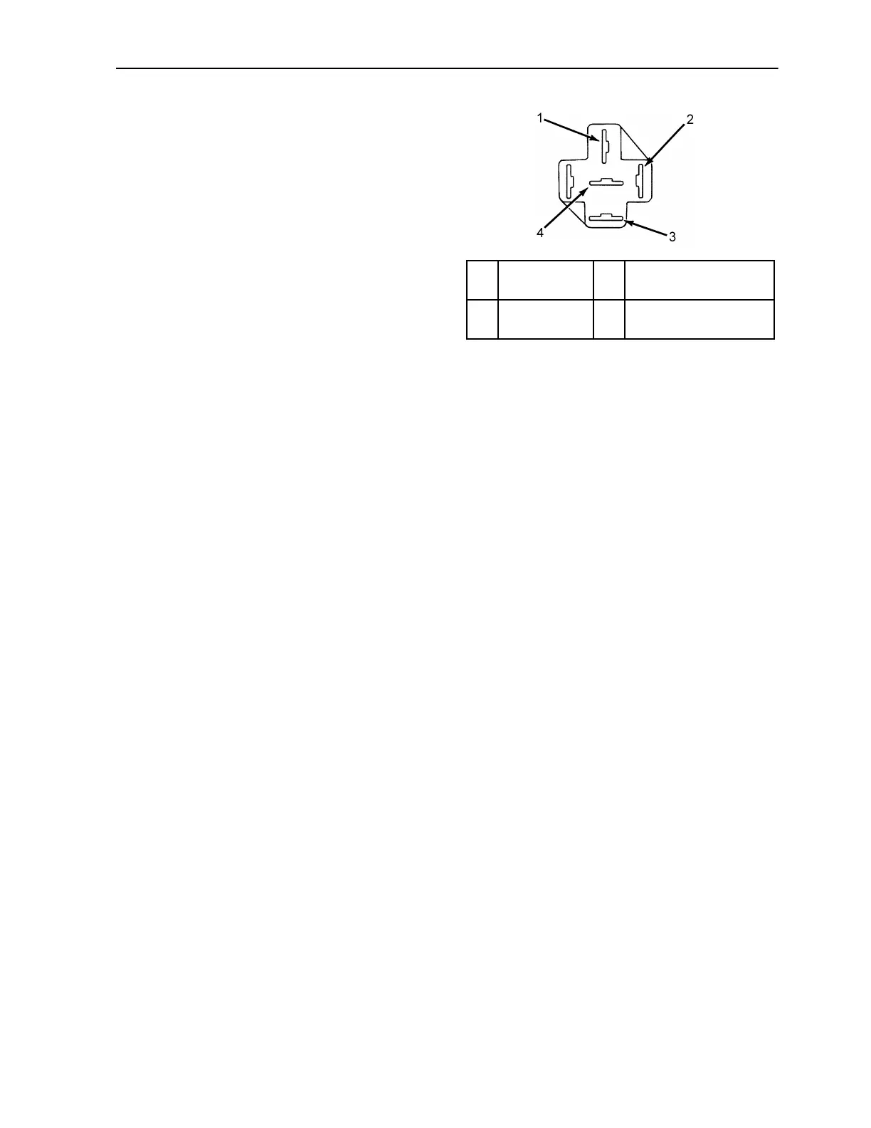
13. Check the voltage on the 8D circuit at the 85
terminal in the fuel solenoid relay socket.
Refer to the following illustration to identify
the terminals in the relay socket.
a. If battery voltage is not present on the 8D
circuit, check the 8D circuit and the
related circuits and components for a fault
(minimum voltage is 10 volts).
b. If battery voltage is present on the 8D
circuit go to step 14.
14. Check the voltage on the 2B circuit at the 30
terminal in the fuel solenoid relay socket.
a. If battery voltage is not present on the 2B
circuit, check the 2B circuit for an open or
a short.
b. If battery voltage is present on the 2B
circuit, go to step 15.
15. Test the relay.
a. Use a jumper to connect the 85 terminal
on the relay to the 2 terminal at the control
circuit.
b. Use another jumper to connect the 86
terminal on the relay to a CH circuit.
c. If the relay does not energize, it is
defective. Replace the relay.
d. If the relay does energize, the timer is
defective. Replace the fuel solenoid timer
PC board.
16. Press the
OFF key, replace the
CYCLE-SENTRY module, and reconnect the
20 wire to the reset switch after completing
the test procedure.
1. 30 Terminal
2B Circuit
3. 87 Terminal
8DP Wire
2. 85 Terminal
8D Wire
4. 86 Terminal to Timer
Figure 33: Relay Socket Terminal Identification
AEA634

 Loading...