Engine Maintenance
103
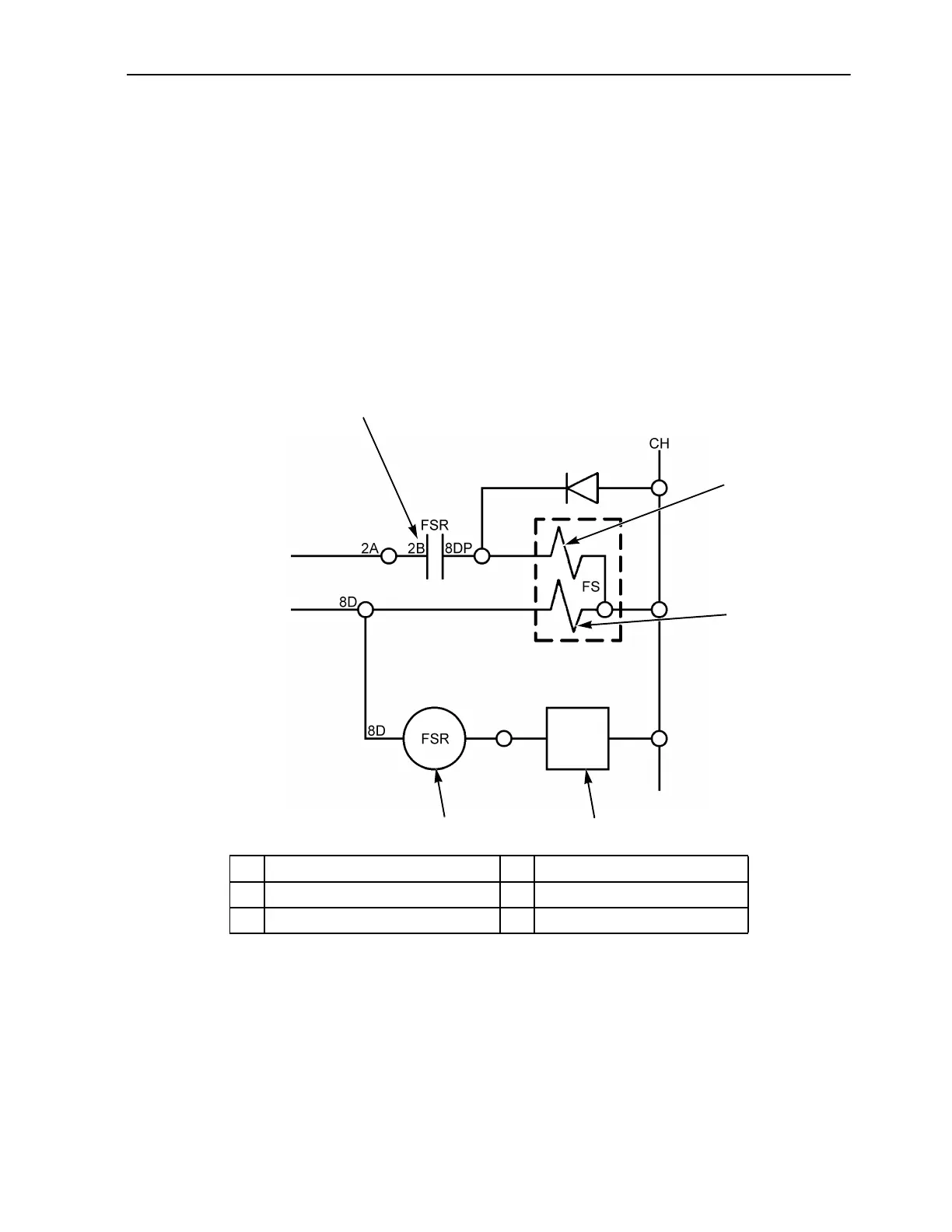
Fuel Solenoid Timer Operation
The fuel solenoid hold-in coil is connected to the
8D circuit. The fuel solenoid relay coil is also
connected to the 8D circuit and it is grounded
through the fuel solenoid timer. The fuel solenoid
pull-in coil is connected to the 2B circuit through
the normally open contacts of the fuel solenoid
relay when the fuel solenoid relay is energized.
When the 8D circuit is energized, it supplies
power to the fuel solenoid hold-in coil and to the
fuel solenoid relay coil. The hold-in coil is
energized and remains energized as long as there
is power on 8D. The fuel solenoid relay is
energized momentarily by the fuel solenoid timer
when the 8D circuit is first energized. After
approximately 2.5 seconds, the fuel solenoid timer
de-energizes the fuel solenoid relay by opening
the circuit to ground.
During the time the fuel solenoid relay is
momentarily energized, the fuel solenoid pull-in
coil is energized by the 2B circuit through the
normally open contacts of the fuel solenoid relay
and the 8DP circuit.
When power is removed from the 8D circuit, the
fuel solenoid hold-in coil is de-energized, and the
fuel solenoid timer resets.
1
2
3
54
AGA310
FSRT
1. Fuel Solenoid Relay Contacts 4. Fuel Solenoid Timer
2. Fuel Solenoid Pull-In Coil 5. Fuel Solenoid Relay Coil
3. Fuel Solenoid Hold-In Coil
Figure 30: Simplified Schematic Diagram of Fuel Solenoid System

 Loading...