Section 2 – SR-2 Hardware Description
Power Side Logic
The outputs listed below supply battery voltage to
energize the device rather than completing the path
to ground. These outputs are protected by a Smart
FET.
Output Function
26 Pilot Solenoid
HG Hot Gas Solenoid
LV1 Loader Valve 1
LV2 Loader Valve 2
WV Water Valve
LQI Liquid Injection Valve
LLS Liquid Line Solenoid
IMPORTANT: All other outputs energize the
associated device by completing the path to chassis
ground. When diagnosing output circuits be sure to
consider if the output is supplying battery voltage or
chassis ground.
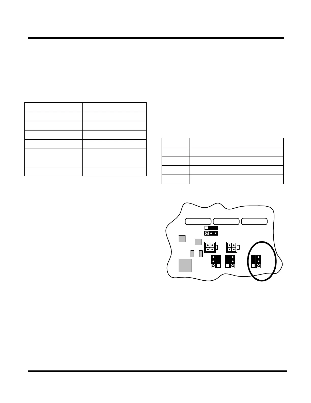
Interface Board Jumpers
Four sets of jumper pins are located on the interface
board. Each set consists of a jumper and three pins.
A graphic next to each set of pins shows the usual
jumper placement. For normal operation, the jumper
must be installed as shown by these graphics. To
change the setting, remove the jumper and place it
as shown on the next page.
Jumper Functions
Jumper Function
J27 Not Used
J101 Cold Start Jumper
J102 Not Used
J103 Not Used
3A
F9
3A
F12
3A
F8
J103
RS232-2
J102
J27
J9 J10
RS232-1
J101
J101 Cold Start jumper
Shown in the normal position
2-14
31 January 2005