Section 5 – SR-2 Diagnostics
87 CHECK SUCTION PRESSURE SENSOR
Page 1 of 1
Alarm Type
Check Alarm
Associated Alarm
Codes
Circuit Description
The 3-wire sensor is supplied with +5 Vdc and ground from the microprocessor. The sensor is located in the
suction line downstream of the ETV. The wiring is located in the Sensor Harness via the SPP-01, SPN-01 and SPI-
01 circuits.
How Alarm is Set
1. The unit is running and the sensor reading is greater than 200 psig for 10 seconds. This test is disabled
while unit is in ETV check.
2. The suction pressure did not rise or fall during an ETV test.
How Alarm is Cleared
This alarm is cleared manually. Clearing the code will cause the unit to shut down and restart to check the
transducer for proper operation by performing a ETV check.
Diagnostic Procedure
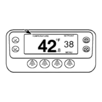
1. Check the suction pressure display using the Gauge Menu.
2. If the suction pressure is not displayed by the microprocessor, unplug the transducer and check for +5 Vdc
between SPP-01 and SPN-01. If 5 volts is not present check the microprocessor, using Service Procedure
A01A.
3. Connect refrigeration gauges to verify that the sensor is not displaying the correct pressure. Replace the
sensor.
4. Check the harness wires SPP-01, SPN-01 and SP-01 for continuity using an ohmmeter.
5-67
02 February 2005