Do you have a question about the Thermo King SLX Series and is the answer not in the manual?
Guide to understanding the manual's structure, including sections on safety, hardware, software, operation, diagnostics, service, and diagrams.
Details critical safety advisories including DANGER, WARNING, CAUTION, and NOTICE classifications for equipment operation.
Covers high voltage precautions, hazardous voltage warnings, and personal protective equipment requirements.
Addresses hazards associated with refrigerants, including pressures, combustibility, and hazardous gases.
Provides essential first aid instructions for refrigerant, oil, engine coolant, battery acid exposure, and electrical shock.
Provides a visual overview of the SR-3 control system components, including HMI, Base Controller, sensors, and switches.
Details the SR-3 Base Controller and SR-3 HMI Control Panel, including their features and compatibility.
Describes various sensors used in the SR-3 control system, including air temperature, coil, ambient, and spare sensors.
Explains the function and operation of refrigeration control components like pressure transducers and solenoids.
Details components related to engine operation, such as coolant sensors, oil pressure switches, and flywheel sensors.
Lists and describes communication ports available on the SR-3 system, including CargoWatch, USB, and ServiceWatch ports.
Explains the complex software instructions for the Base Controller and HMI, covering input examination and output control.
Outlines the HMI menu hierarchy: Standard Display, TemperatureWatch, Main Menu, Maintenance Menu, and Guarded Access.
Covers programmable features like temperature units, setpoints, fuel saver, defrost settings, and language options.
Details the configuration and viewing of unit hourmeters, including reminders and service due dates.
Provides details on configurable features, including choices, factory settings, exceptions, and descriptions.
Allows modification of Cycle Sentry defaults for battery charge current and unit restart on battery voltage.
Configures defrost operation for maximum performance, including intervals and duration.
Enables selection and display of multiple languages for the HMI Control Panel.
System for tailoring temperature profiles for efficient operation, accessible via Guarded Access or WinTrac.
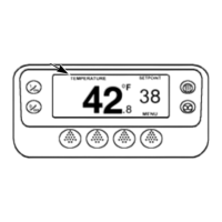
Details the Human/Machine Interface panel, its display, hard keys, and soft keys for unit operation.
Explains how to change setpoints, including numerical and named product options.
Describes how to switch between Cycle Sentry and Continuous modes for unit operation.
Instructions for accessing and viewing unit gauges via the HMI Control Panel.
Details how to access and navigate various Main Menu choices for unit control.
Covers inserting, accessing, downloading, and removing USB flash drives for software and data transfer.
Explains how to view and clear active alarms, including log, check, prevent, and shutdown alarms.
Details the functionality of the CargoWatch Data Logger, including sensor support and start of trip markers.
Describes how to manually switch between diesel and electric modes, or automatic switching if enabled.
Explains manual switching from electric to diesel mode and the implications of standby power availability.
Guides on initiating and performing Pretrip Tests to verify unit operation and identify potential issues.
Provides an overview of diagnostic routines, helpful hints, and general alarm code information for the SR-3 system.
Details essential precautions to prevent electrostatic discharge damage to electronic components.
Lists and describes general alarm codes, including alarm type, associated codes, and diagnostic procedures.
Details checks for the evaporator coil sensor, including soft/hard failures and diagnostic steps.
Covers issues with the return air sensor, including soft/hard failures, sensor grades, and diagnostic procedures.
Addresses problems with the discharge air sensor, including soft/hard failures, sensor grades, and diagnostic steps.
Explains the causes and diagnostic procedures for high discharge pressure alarms.
Details the process for checking sensor calibration and clearing associated alarms.
Covers diagnostic procedures for alarms indicating the engine failed to crank.
Provides diagnostic steps for alarms related to the engine failing to start.
Details checks for the cooling cycle, including temperature differentials and refrigerant levels.
Explains the causes and diagnostic procedures for cooling cycle faults.
Covers diagnostic procedures for heating cycle faults and related alarm codes.
Provides steps for checking engine RPM, including high and low speed checks.
Details diagnostic procedures for electric motor failures, including checking components and voltage.
Outlines checks for engine coolant temperature, including coolant level and radiator airflow.
Covers diagnostic procedures for fuel system issues, including checking fuel level and filter.
Provides diagnostic steps for the hot gas bypass circuit, including current draw and LED diagnosis.
Details checks for restricted airflow and the spare sensor used for blocked air chute detection.
Covers diagnostic procedures for belt or clutch issues, including slippage and alternator operation.
Explains diagnostic steps for low battery voltage, including checking battery condition and connections.
Provides diagnostic procedures for engine stopped alarms, covering various checks and test modes.
Addresses issues where OptiSet Plus configuration in Base Controller mismatches HMI Control Panel.
Procedure to confirm proper operation of the SR-3 Base Controller using diagnostic tools.
Procedure to confirm proper operation of the HMI Control Panel using the diagnostic tool.
Details on performing HMI Control Panel self-tests using the built-in Display Self Test.
Procedure to retrieve and record sensor grades and programmable features before controller replacement.
Step-by-step guide for replacing the SR-3 Base Controller, including important notes and connection checks.
Instructions for replacing the HMI Control Panel, including software and connection verification.
Procedure to set sensor grades and programmable features according to customer specifications.
Procedure for performing a cold restart on the SR-3 Base Controller using WinTrac Service Tool.
Guides on setting sensor grades for return, discharge, and spare sensors for accurate calibration.
Procedure for updating Base Controller software using a computer and WinTrac Service Tool.
Procedure for updating HMI Control Panel software using a computer and WinTrac Service Tool.
Details on testing temperature sensors, including hard and soft failures and replacement procedures.
Procedure for testing suction and discharge pressure transducers, including voltage and continuity checks.
Procedure to check the electrical operation of the ETV using the Base Controller and diagnostic tools.
Procedure to check the mechanical operation of the ETV using a stepper valve tester.
Illustrates correct procedures for checking harness continuity on equipment with solid state devices.
Details hardware versions, service part numbers, label identification, software requirements, and compatibility.
Provides information on HMI hardware versions, part numbers, label identification, software requirements, and compatibility.
Information on the diagnostic tool, its features, requirements, and software availability.
Explains how the SR-3 HMI Control Panel controls power up/down operations and data logging.
Describes the power-up sequence for the unit via the HMI Control Panel.
Details the power-up sequence initiated by a remote control panel on units with an HMI Control Panel.
Explains the power-down sequence initiated by a remote control panel on units with an HMI Control Panel.
Lists common HMI messages, their causes, and potential issues like communication failures.
Provides a list of Base Controller software revisions, their features, and interchangeability.
Details HMI Control Panel software revisions, supported languages, and interchangeability.
Lists available SR-3 control system schematic and wiring diagrams, including drawing numbers and titles.
| Microprocessor Controller | Yes |
|---|---|
| Power Supply | 12 VDC |
| Display | LCD |
| Communication Protocol | CAN bus |
| Mounting | mount |