Section 5 – SR-2 Diagnostics
45 CHECK HOT GAS OR HOT GAS BYPASS CIRCUIT
Page 1 of 1
Alarm Type
Check or Shutdown Alarm (Pretrip Only)
Associated Alarm
Codes
None
Component Description and Location
The hot gas/hot gas bypass solenoid is located in the condenser section next to the receiver tank. It is a normally
closed valve. This valve is only used on ETV units.
Circuit Description
The hot gas/hot gas bypass solenoid circuit is a two wire circuit. The HG-01 wire connects the interface board
connector J7 pin 5 to one side of the hot gas/hot gas bypass solenoid. The CHHG wire connects the other side of
the solenoid to chassis ground at the ground plate near the unit battery. The solenoid is not polarity sensitive. The
switch wires are routed in the Main Harness. A Smart FET on the interface board supplies power to the HG-01
circuit.
How Alarm is Set
1. This alarm is set if the measured shunt current is incorrect during non running Pretrip Test. Current is
measured with the output on and off.
2. The alarm is set as a Check alarm if the current is not within specifications when the solenoid is energized.
3. The alarm is set as a Shutdown alarm if the current does not return to 0 when the device is de-energized.
How Alarm is Cleared
This alarm is cleared manually.
Diagnostic Procedure
1. Check the operation of the hot gas/hot gas bypass circuit using Interface Board Test Mode. Be sure the
hot gas LED 10 lights.
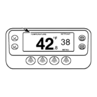
2. Use the HMI control panel amps gauge to check the current drawn by the hot gas/hot gas bypass solenoid,
while operating the hot gas/hot gas bypass solenoid with Interface Board Test Mode. The current draw
should be approximately 1.1 amps.
3. Energize the hot gas/hot gas bypass solenoid, using Interface Board Test Mode. Check for battery voltage
on the HG-01 circuit. If voltage is present at the hot gas/hot gas bypass solenoid, and no current was
measured in the step above, replace the hot gas/hot gas bypass solenoid coil.
5-51
02 February 2005