Section 2 – SR-2 Hardware Description
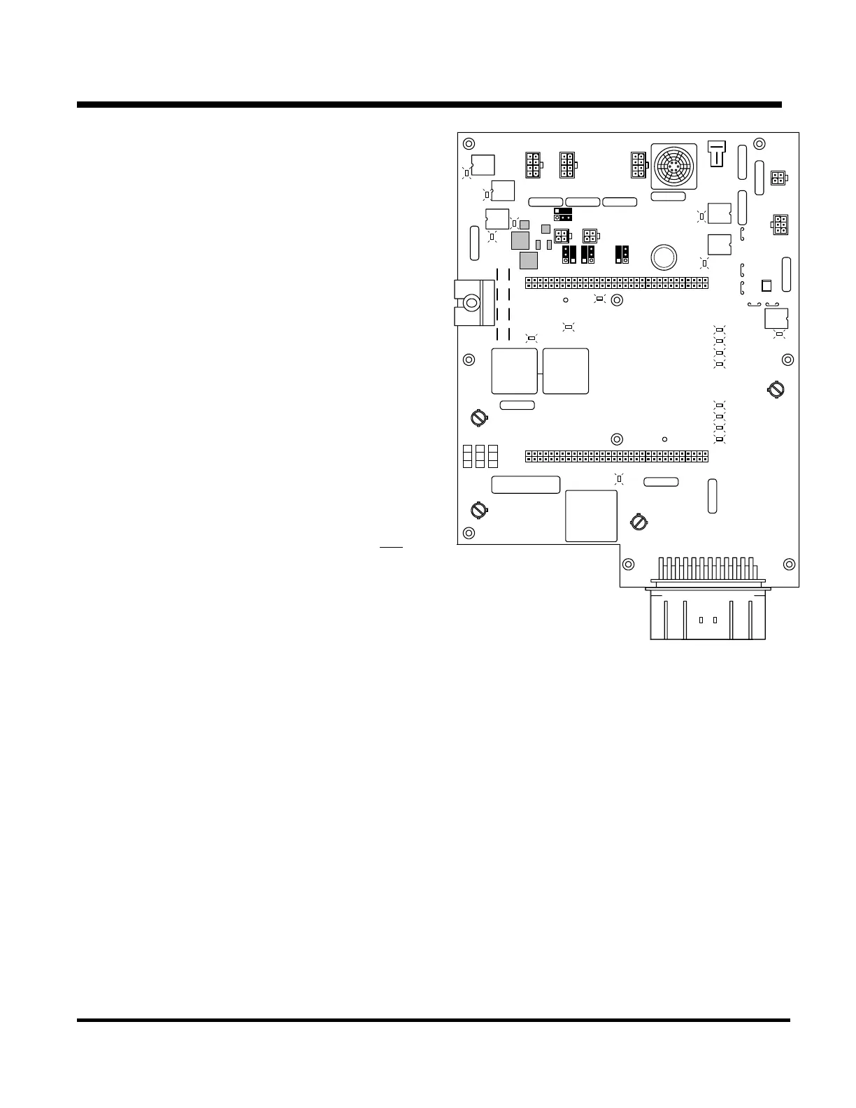
INTERFACE BOARD
The interface board provides the interface between
the microprocessor and the unit components such
as solenoids valves, and motor contactors. It also
provides overcurrent and short circuit protection for
the controls and components.
The microprocessor controls the operation of the
unit through the control relays and Smart FETs on
the interface board. The relays control power to the
high amperage loads. The Smart FETs control
power to the lower amperage loads. Each relay is
individually fuse protected. The Smart FETs are
self-protecting An LED next to each relay or Smart
FET is illuminated when the relay or FET is
energized by the microprocessor. With relays the
LED lights only when the relay coil is energized
and
the relay contacts have transferred to the energized
position.
The interface board is plugged directly into the
microprocessor and secured with mounting
hardware. The main components on the interface
board are the control relays, fuses, LEDs to indicate
relay or output states, preheat buzzer, jumpers,
current shunt, smart FETs, and the wiring harness
connectors. The only user serviceable components
on the interface board are the fuses and jumpers.
K5
K8
15A
10A 15A
1A
K6 K7
K2
CH
J7
1
CAN 3
F1
F10
F2
F3
F6
ON/OFF
SWITCH
LED22
J4
2A
F7
3A
F9
3A
F12
3A
F8
CAN 2 CAN 1
J103
RS232-2
J102
J101
J27
10A
F11
K4
K3
H
2A
2
60A
F5
40A
8D 8DP
8S
8
DG
7D29
LED17
LED18
LED20
LED19
LED8
LED9
LED10
LED11
LED24
LED25
LED5
LED4
LED7
K9
K1
LED23
LED6
LED3
REMOTE LIGHT
ELECTRIC
J8
J6
J14
J13 J12
J9
J10
J15
GM1
F4
2A
F20
F13
F15
RS232-1
GM2
J24
J25
J3
J26
J23
2A
F12
LED21
LED26
SR2 Interface Board
2-11
31 January 2005



 To Next Page