Section 2 – SR-2 Hardware Description
MICROPROCESSOR
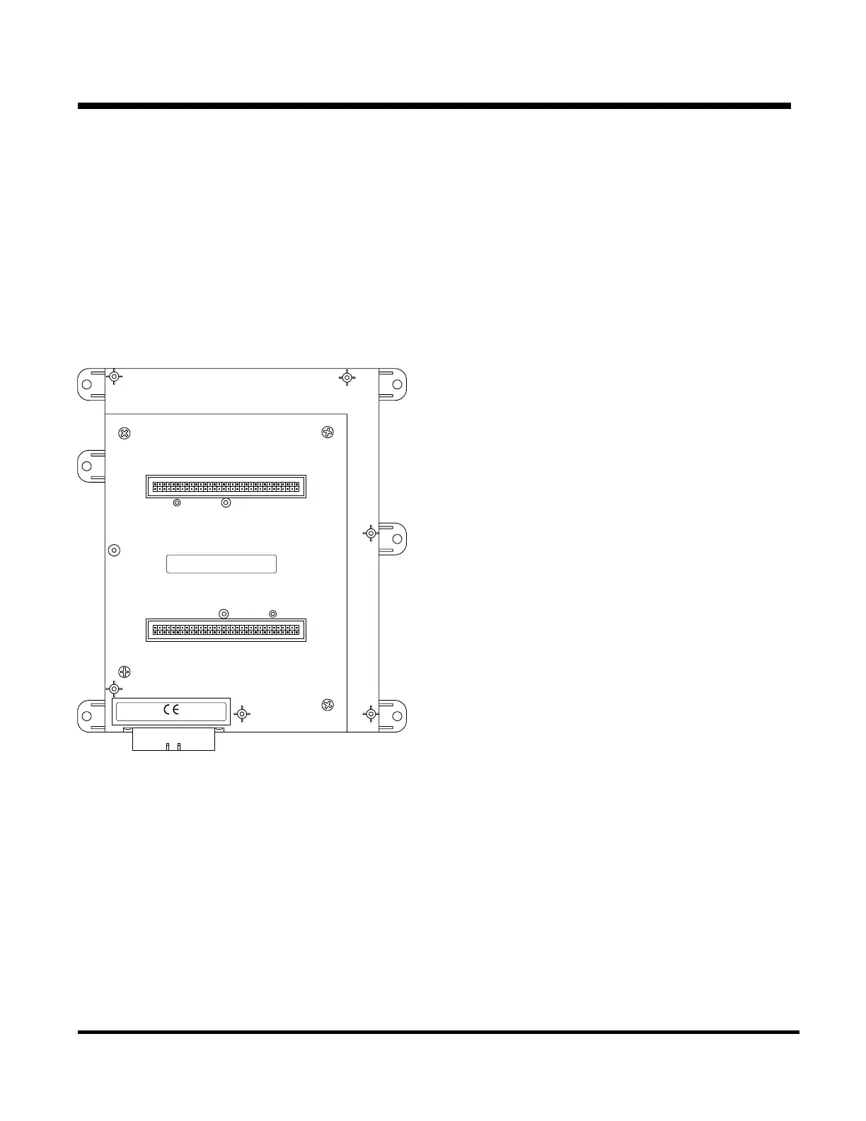
The SR2 microprocessor is located on the rear
panel of the control enclosure. Two multi-pin
interface board connectors (J1 and J2) are located
on the front of the microprocessor. A 37 pin sensor
connector (J3) is located at the lower left of the
microprocessor. The J3 connector is used for
sensor inputs.
J1
J2
J3
ASS'Y P/N: 1E19311G01
S.P. P/N: 45-2015
S/N:XXXXXXXXXXX
REV. B000
ASS'Y P/N: 1E19308G01
S.P. P/N: 45-2013
S/N:XXXXXXXXXXX
REV. B000
A ND
C
SR2 Microprocessor.
The J1 and J2 connectors are used to mate the
microprocessor and interface board into a
single assembly.
Microprocessor Operation
The microprocessor is the heart of the control
system. It consists of the microprocessor, software,
memory, inputs and outputs. The software provides
the required operating and control functions and
supports the Service Watch Data Logger.
Inputs are used to supply power and system
information to the microprocessor. The
microprocessor uses the outputs to control the
operation of the unit components. The
microprocessor has no user serviceable
components.
Real Time Clock
The real time clock is located in the HMI Control
Panel. The time is supplied to the microprocessor
each time the unit is turned on. If the
microprocessor is changed the clock setting will be
automatically supplied to the microprocessor when
the unit is turned on.
Programmable Features
The settings of all programmable features are held
in non-volatile memory in the microprocessor. The
settings are supplied to the HMI Control Panel each
time the unit is turned on. If the microprocessor is
changed, all programmable features must be
reprogrammed.
2-9
31 January 2005

 Loading...