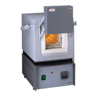
The Thermo Scientific Type 1700 Furnace is a large-capacity laboratory and heat-treating furnace designed for a range of thermal applications. This operation manual and parts list, specifically for the Series 85 Gray models, provides comprehensive information on its use, maintenance, and safety.
Function Description
The Type 1700 furnace is primarily used for general laboratory procedures and heat treating. It features a heating chamber and a two-section counter-weighted door. The chamber is heated by four electric resistance heaters embedded in a special refractory cement, and it is insulated with firebrick and ceramic fiber insulation to minimize heat loss. A key safety feature is the door safety switch, which removes power from the heating elements when the door is opened, preventing accidental exposure to high temperatures. Power is automatically restored when the door is closed.
Important Technical Specifications
The furnace is available in several models with different voltage requirements:
- 240 volt models: FA1730 & FA1730-1, FA1736 & FA1736-1, FA1738 & FA1738-1
- 480 volt models: FA1740 & FA1740-1, FA1746 & FA1746-1, FA1748 & FA1748-1
- 208 volt models: FA1738 & FA1738-1, FA1748 & FA1748-1
Standard models are designed for continuous use (more than 3 hours) at temperatures from 300°F (150°C) to 1800°F (982°C), and for intermittent use (less than 3 hours) at temperatures from 1800°F (982°C) to 2000°F (1093°C). High temperature (-1) models extend these ranges, allowing continuous use from 300°F (150°C) to 1950°F (1066°C) and intermittent use from 1950°F (1066°C) to 2150°F (1177°C).
The furnace does not come with a power cord due to its high current requirements, which exceed the capacity of ordinary power cords and standard wall supplies. Installation requires a competent, qualified electrician to ensure compatibility with furnace specifications, power source, and grounding code requirements. For supply connections, 10 AWG or larger wires suitable for at least 200°C are recommended.
Usage Features
- Site Selection: The furnace should be installed on a sturdy surface with adequate space for ventilation, maintaining at least six inches of clearance from combustible walls to prevent fire hazards.
- Loading: For optimal results and uniform heating, the load should not occupy more than two-thirds of any dimension of the chamber. A clearance of 3/4" to 1" should be maintained between the load and side heating elements. Loads should be placed on a hearth plate (PHX2) or an optional shelf (PH42X1). Small parts should be spread throughout the middle two-thirds of the chamber. Objects must be kept away from the thermocouple. Insulated tongs and mittens, along with safety glasses, are essential for safe loading and unloading.
- Door Safety Switch: This critical safety feature ensures that power to the heating elements is cut when the door is open. Regular testing of the door switch is recommended to ensure proper operation.
- High Temperature Element Protection: For high-temperature (-1) models, the element wire is protected by an aluminum oxide layer that forms on its surface during operation at temperatures of at least 1800°F (982°C) for approximately 8-10 hours. This oxide layer provides strength and prevents contamination, which is crucial for the heating unit's overall life. Any substance contacting the heating element and preventing oxide formation can lead to premature failure.
- Temperature Control: The furnace requires an automatic temperature controller (not included with the furnace itself), and users must consult the controller's operating instructions for correct operation.
Maintenance Features
- Safety First: Before any maintenance or servicing, the furnace must be disconnected from the power supply to avoid electrical shock. Only maintenance described in this manual should be performed; for other issues, an authorized dealer or the factory should be contacted.
- Preventive Maintenance:
- Cleanliness: Maintaining a clean furnace is vital. Running the furnace empty at 1600°F for 3-4 hours occasionally helps burn off contamination from insulation and elements.
- Contamination Removal: Contamination is a major cause of element failure. Fume-forming materials, such as cutting oil from tool steel, should be removed before heating whenever possible.
- Element Life: Repeated heating and cooling can reduce element life. If the furnace is to be used again within a few hours, it is best to keep it at the operating temperature or a reduced level (e.g., 500°F/260°C).
- Replacing Heating Elements:
- Disconnect power.
- Remove the back terminal cover.
- Loosen the nut on the terminals of the element to be replaced, noting wire placement. Corroded hardware should be replaced.
- Straighten the leads of the old element.
- Open the door and pull out the defective element.
- Slide the new element into place, threading leads through the insulating bushing.
- Bend the elements across the "U" shaped terminal clamp washer, replace the adjacent element lead, and tighten the nut securely. Cut off excess lead wire. Use rounded nose pliers to bend new wires, avoiding nicks or gouges.
- Replace the back terminal cover.
- Reconnect power.
- Replacing Thermocouple (Type F Platinel II - Supplied with Thermolyne Controllers):
- Disconnect power.
- Remove the back terminal cover (four screws), noting wire placement.
- Loosen the screws holding the thermocouple to the terminal block and pull out the old thermocouple from the porcelain insert.
- Insert the new thermocouple into the porcelain insert.
- Insert the thermocouple lead tagged positive (+) into the terminal block marked positive (+).
- Insert the remaining thermocouple lead into the terminal on the block marked negative (-), and tighten set screws securely.
- Replace the back terminal cover.
- Reconnect power.
- Replacing Door Switch:
- Disconnect power.
- Remove the door counterweight by removing the set screw and pulling.
- Remove the four screws from the door switch cover and slide the cover off.
- Remove the two screws from the door switch and desolder its two wires.
- Insert the new door switch.
- Resolder wires to the new door switch.
- Replace the cover.
- Replace the door counterweight.
- Reconnect power.
Troubleshooting
The manual provides a detailed troubleshooting guide covering common issues such as:
- Power light not illuminating: Check power connections, controller malfunction, door not fully closed, or door switch malfunction.
- Furnace not heating: Check power source, fuse, electrical hook-up, controller malfunction, or burned-out heating elements (number varies by voltage).
- Slow heat-up: Check for low line voltage, heavy load in the chamber, or wrong/burned-out heating elements.
- Temperature erratic or no control: Controller malfunction or incorrect thermocouple.
- Door switch not cutting power: Realign or replace the door switch.
- Repeated element burn-out: Overheating, heating harmful materials (which can cause contamination), controller malfunction, wrong element, oxidized thermocouple, or contamination from previous burn-out.
- Inaccurate temperatures: Incorrect/oxidized/contaminated thermocouple, controller malfunction, poor thermocouple connection, improper loading, poor ventilation of the controller, or reversed polarity of thermocouple/extension wires.
Ordering Procedures
When ordering service or replacement parts, users should refer to the Specification Plate for the complete model number, serial number, and series number. Parts can be ordered from an authorized Thermo Scientific dealer or directly from the factory. A "Return Materials Authorization" (RMA) number is required before returning any materials.
Warranty
The product comes with a one-year limited warranty against defects in materials and workmanship from the date of sale or purchase by the original retail customer. The manufacturer disclaims all other warranties, including design, merchantability, and fitness for a particular purpose. Warranty inspections must be performed by an authorized representative. For defects covered by the warranty, the manufacturer will provide free replacement parts. For products sold in the continental United States or Canada, free labor for repair with replacement parts is provided for 90 days from the commencement date. The warranty is void if repairs are made by unauthorized parties, misuse occurs, or unauthorized replacement parts are used. Heating elements are warranted if failure is due to factors other than excessive high temperature or contamination, requiring return to the factory for inspection. The manufacturer is not liable for direct, indirect, special, incidental, or consequential damages.