EasyManua.ls Logo

Thermo Scientific GENESYS 20 User Manual

Thermo Scientific GENESYS 20
205 pages
To Next Page IconTo Next Page
Page #1 background imageLoading...
Page #1 background image
Artisan Technology Group is your source for quality
new and certied-used/pre-owned equipment
FAST SHIPPING AND
DELIVERY
TENS OF THOUSANDS OF
IN-STOCK ITEMS
EQUIPMENT DEMOS
HUNDREDS OF
MANUFACTURERS
SUPPORTED
LEASING/MONTHLY
RENTALS
ITAR CERTIFIED
SECURE ASSET SOLUTIONS
SERVICE CENTER REPAIRS
Experienced engineers and technicians on staff
at our full-service, in-house repair center
WE BUY USED EQUIPMENT
Sell your excess, underutilized, and idle used equipment
We also offer credit for buy-backs and trade-ins
www.artisantg.com/WeBuyEquipment
REMOTE INSPECTION
Remotely inspect equipment before purchasing with
our interactive website at www.instraview.com
LOOKING FOR MORE INFORMATION?
Visit us on the web at www.artisantg.com for more
information on price quotations, drivers, technical
specications, manuals, and documentation
Contact us: (888) 88-SOURCE | sales@artisantg.com | www.artisantg.com
SM
View
Instra

Table of Contents

Question and Answer IconNeed help?

Do you have a question about the Thermo Scientific GENESYS 20 and is the answer not in the manual?

Thermo Scientific GENESYS 20 Specifications

General IconGeneral
TypeUV-Vis Spectrophotometer
Spectral Bandwidth5 nm
Photometric Range-0.3 to 3.0 A
DetectorSilicon Photodiode
Power Requirements100-240 VAC, 50/60 Hz
Photometric Accuracy±0.005 A at 0.5 A
Light SourceTungsten-Halogen Lamp
DisplayLCD
Sample HolderCuvette Holder

Summary

Section 1 - Description

GENESYS 20 Components

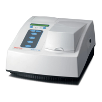
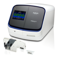
Identifies the main physical parts of the GENESYS 20 spectrophotometer.

Keyboard Layout and Functions

Describes the layout and operational functions of the instrument's keyboard.

Section 2 - Specifications

Instrument Specifications and Environment

Details the performance, physical characteristics, and operating/storage conditions.

Section 3 - Installation and Performance Checks

Performance Checklist

Provides a checklist for instrument installation and performance verification.

Section 4 - Troubleshooting

Error Messages and Diagnosis

Lists and explains error messages and provides general troubleshooting guidance.

Common Problems and Solutions

Lists typical problems, their symptoms, and probable causes for the instrument.

Section 5 - Routine Maintenance

Lamp Replacement Procedure

Step-by-step instructions for replacing the instrument's lamp.

Fuse Replacement

Procedure for replacing the instrument's fuse.

Section 6 - Optical Description

Optical Path and Components

Explains the light path and components within the spectrophotometer.

Section 7 - Optical Alignment

Filter and Lens Assembly Alignment

Details the procedure for aligning the filter and lens assembly.

Alignment Tool Usage

Describes how to fabricate or use an alignment tool.

Section 8 - Electrical Circuit Description and Adjustment

Circuit Board Descriptions

Describes the Power Supply, Main Board, and Detector Board circuitry.

Analog and Motor Control Circuits

Explains analog signal processing, Mono Drive, and Filter Wheel control circuits.

Section 9 - Disassembly and Replacement

External Covers and Lamp Door

Instructions for removing external covers, lamp door, and printer cover.

Main Cover and Sample Compartment

Procedures for removing the main cover assembly and sample compartment cover.

Rear Panel and Front Panel Components

Covers removal of the rear panel and access to front panel components (display/keypad).

Main Circuit Board and Power Systems

Covers removal/replacement of the Main PCB, Power Entry Module, and Power Supply.

Optical Path Assemblies

Details disassembly of Detector, Entrance Slit, Lamp Socket, and Filter/Lens assemblies.

Motor and Limit Switch Components

Covers replacement of Filter Wheel Motor, Lamp Spring, and Limit Switch.

Section 10 - Accessories

Accessory Options

Lists available optional accessories for the GENESYS 20 spectrophotometer.

Section 11 - Spare Parts and Special Tools

Spare Parts List

Lists part numbers for common replacement components.

Service Tools

Lists specialized tools required for maintenance and repair.

Section 12 - Drawings and Schematics

Mechanical Assemblies Listing

Lists mechanical assemblies with part numbers and sheet references.

Electrical Schematics and Board Layouts Listing

Lists electrical schematics and board layouts with part numbers and sheet references.

Section 13 - Update Information

Fan and Guard Component Update

Details changes to fan and guard components due to ESD testing.

Troubleshooting Updates

Explains "Sample Too Bright" error and component updates for it.

PCB Replacement Notes

Instructions for handling the EEPROM when replacing the Main PCB.

Lamp Eccentric Adjustment Change

Describes changes to the lamp alignment adjustment mechanism.

Related product manuals