Do you have a question about the Thermo Scientific 20-35-NM-DIN and is the answer not in the manual?
| Junction | Grounded |
|---|---|
| Interface | Miniature DIN |
| Type | Thermocouple |
| Measurement Range | -200°C to +1200°C |
| Operating Temperature | -40°C to +85°C |
Describes typical use cases and conditions for the tilt sensor system.
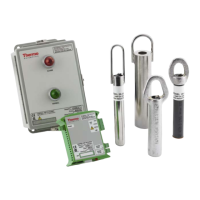
Lists and details specifications for the different available tilt sensor probe models.
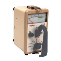
Details specifications for the Model 20-35-NM-F and 20-35-NM-DIN control units.
Explains the various symbols used throughout the manual for clarity.
Steps for mounting and installing the control unit enclosure.
Guidance on correctly positioning and installing the tilt sensor probe.
Instructions for making the electrical connections to the system.
Illustrates system operation in various material flow and level scenarios.
Configuring system parameters, function modes, and switch settings.
Guidelines on when maintenance or functional checks are required for the system.
Procedures for checking the operation of both control unit models.
How to order replacement parts and the required information for the process.
Steps for preparing the system for long-term shutdown and storage.
Instructions for safely dismantling the equipment and disposing of waste materials.
Shows the location of labels on the Model 20-35-NM-F control unit.
Shows the location of labels on the Model 20-35-NM-DIN control unit.
Shows the location of labels on the tilt sensor probes.