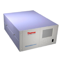
Do you have a question about the Thermo Scientific MIRAN 205B Series and is the answer not in the manual?
| Brand | Thermo Scientific |
|---|---|
| Model | MIRAN 205B Series |
| Category | Measuring Instruments |
| Language | English |
Overview of MIRAN SapphIRe analyzers, infrared instruments for monitoring workplace environments.
Detailed technical specifications of the SapphIRe analyzer, including measurement range, output, and wavelength.
Conditions for optimal operation, storage, and transportation of the analyzer, including temperature and humidity.
Details on the physical dimensions, materials, and weight of the analyzer unit.
Information on electrical safety certifications and application conditions for intrinsically safe models.
Instructions for removing the instrument from packaging and checking for damage or shortages.
Location and importance of data plates for instrument identification and technical contact.
Details on installing and using the optional wand and filters for sample analysis.
Information on the analyzer's charger and power supply unit for operation and battery recharging.
Procedure to recalibrate the battery's internal computer chip for accurate run-time indication.
Process to prevent battery memory effect and maintain optimal run-time potential.
Details on the analyzer's power and signal connection panel and its various ports.
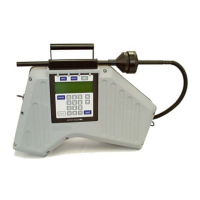
Overview of the analyzer's front panel controls, display, and key functions.
Accessing and using the analyzer's control menu for various functions like backlight and pump control.
Steps to turn on the analyzer and navigate through the initial menus for operation.
Identifying and understanding error messages displayed by the analyzer for troubleshooting.
Procedure for adjusting the analyzer's pathlength setting for optimal measurement.
Procedure and cautions for zeroing the analyzer in the analysis area for accurate measurements.
Steps to start taking measurements after zeroing or if the zeroing procedure is skipped.
Function to save measurement values for later download to a PC or printer.
Explanation of display indicators for errors and faults encountered during analysis.
Feature to scan all measurable wavelengths for analysis or calibration development.
Main menu for configuring analyzer settings like calibration, preferences, gas units, and analysis setup.
Mode to check zero, calibrate temperature sensor, or load performance verification.
Menus to configure various operational features and display selections of the analyzer.
Overview of the four menus used for configuring analysis setup parameters.
How to configure the state of the analyzer's alarms, including high, low, and STEL setpoints.
How to specify analysis compensations for temperature, pressure, reference, and humidity.
How to turn the passcode on/off or change the passcode for analyzer security.
How to configure location modes, sorting, and insertion methods for data logging.
Modifying parameters like gas unit, alarms, and STEL time for a selected application.
Extensive view and edit procedure for the currently selected application parameters.
Creating and managing sites for logging data within the analyzer's memory.
Reusable identifiers for data within a site, with types: Standard, Supplemental, Added.
Procedure to select a site from logged data for reporting or transfer.
Options for printing reports, including full or partial setup data.
Connecting to a PC for data transfer, changing modes, and baud rates.
Options for clearing logged data, sites, locations, and report definitions from memory.
Storage, replacement, and maintenance recommendations for the zero gas filter.
Filter life, clogging symptoms, and replacement criteria for the particulate filter.
Maintenance, charging, and model compatibility information for the analyzer's battery pack.
Preventing damage to cell windows from high concentrations of specific compounds.
Overview of firmware updates, enhancements, and the process of uploading them.
Step-by-step instructions for updating the analyzer's firmware.
How to download current setup configuration before performing a firmware update.
Steps to upload new firmware to the analyzer via a PC and serial port connection.
Verifying analyzer performance using a closed loop system with a pure sample.
Detailed steps for conducting a field performance verification test on the analyzer.
Evaluating displayed readings against tolerances and identifying potential causes for deviations.
How the MIRAN SapphIRe analyzer measures concentrations using infrared spectroscopy principles.
How molecular motion and vibration relate to infrared absorption for analysis.
Identifying compounds by analyzing their unique infrared absorption spectra.
Measuring absorption intensity and its relation to gas concentration and pathlength.
The relationship between absorption, concentration, and pathlength in spectroscopy.
Explanation of the analyzer's internal components and their functions in infrared analysis.
Overview of the standard report format including header, gas data, and footer.
How to create a custom report format by modifying or sketching a new layout.
Customizing the report header with product name, date, time, and site using coded formats.
Explanation of the coded format for reporting gas data for each location and sample type.
Defines user-entered information format for report entries, detailing field types and parameters.
Seller's warranty terms, period, exclusions, and limitations for the products.
Configuration of I/O for hazardous locations and applicable electrical safety specifications.
Warnings and considerations for operating the analyzer in hazardous areas.
Overview of scan/calibration procedures, requirements, and types of scans.
Steps to create a logging site for data collection and calibration.
Procedure for performing peak pick or full spectrum scans on the analyzer.
Steps to transfer logged scan data from the analyzer to a PC via serial connection.
Calculating injection volumes and performing calibration with known concentrations.
Using Microsoft Excel to generate P-Matrix for calibration based on absorbance and concentration data.
Steps to input P-Matrix into the analyzer and verify the calibration accuracy.
Table of wavelength and P values used for humidity compensation calculations.
Overview of the kit for verifying analyzer performance, including gas concentrations and safety.
Steps to configure the analyzer for the 'CALCHECK' performance verification application.
Procedure for performing the gas challenge test, including zeroing the analyzer and observing readings.
List of main parts included with the analyzer and their corresponding part numbers.
List of accessories compatible with the analyzer and their part numbers.
Using Hyperterminal as a terminal program for PC communication with the analyzer.
List of standard compounds, their library designation, HRL, detection limits, and accuracy.
