24 40.019.003 - rev 09 - 2018
IMA
ENGLISH
AMI1102 - 60 .ver - 300.910.0442
English
7 SPARE PARTS
For operation we advise you to have spare parts
in store. See table B in the appendix.
8 TECHNICAL INFORM ATION
• For the technical specifications, see table C
in the appendix at the back of this book.
9 INSTALLATION OF ACCESSORIES
9.1 Flue (Fig. 4)
The heater is provided with a flue connection.
1. Fit the flue (B) in the flue connection (C) of
the heater.
2. Fit a rain cover (A) at the end of the flue for
outside use.
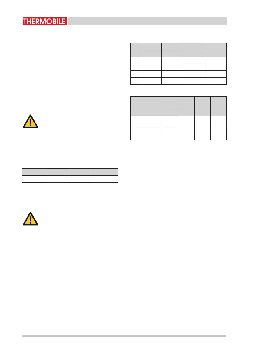
9.2 Diameter of the flue connection
/i
9.3 Outlet hose
An outlet hose must be fitted to the outlet of the
heater, in orde
r to blow heated air to a remote
area away from the heater.
Please contact the dealer for information about
maximum lengths of outlet hoses, bends,
distribution pipes and hose clamps.
9.4 Diameters of outlet hoses
/i
N = Number of outlets
/i
9.5 Room thermostat
See the instructions of the room thermostat.
10 EC DECLARATION OF CONFORM ITY
For the E C declaration of conformity, go to
www.thermobile.nl.
Caution
The flue must point upwards. Never
place the flue horiz ontally. An angle of
45° is acceptable. The minimum length
of the flue is 1000 mm.
IM A 61 IM A 111 IM A 150 IM A 2 0 0
180 mm 200 mm 200 mm 200 mm
Caution
Check the temperature resistance of the
used hose.
N IM A 61 IM A 111 IM A 150 IM A 2 0 0
mm mm mm mm
1 Ø 400 Ø 500 Ø 500 Ø 600
2 Ø 300 Ø 365 Ø 365 Ø 500
3 --- Ø 365
4 - Ø 300 Ø 300 Ø 300
Back
pressure of
fan
IM A
61
IM A
111
IM A
150
IM A
2 0 0
Pa Pa Pa Pa
R (230 V, 1
phase)
250 300 300 300
R HP (400 V, 3
phases)
- 500 500 500