Page 2 / 8 Issue date: 24.11.2017
Thermokon Sensortechnik GmbH, Platanenweg 1, 35756 Mittenaar, Germany · tel: +49 2778 6960-0 · fax:-400 · www.thermokon.com · email@thermokon.de
JOY_Fancoil_EC_3AO_Modbus_Datasheet_v1.6.0+_en.docx © 2017
Notes on Disposal
As a component of a large-scale fixed installation, Thermokon products are intended to be used permanently as
part of a building or a structure at a pre-defined and dedicated location, hence the Waste Electrical and Electronic
Act (WEEE) is not applicable. However, most of the products may contain valuable materials that should be
recycled and not disposed of as domestic waste. Please note the relevant regulations for local disposal.
Remarks to Room Sensors
Location and Accuracy of Room Sensors
The room sensor should be mounted in a suitable location for measuring accurate room temperature. The accuracy of the
temperature measurement also depends directly on the temperature dynamics of the wall. It is important, that the back plate is
completely flush to the wall so that the circulation of air occurs through the vents in the cover. Otherwise, deviations in
temperature measurement will occur due to uncontrolled air circulation. Also the temperature sensor should not be covered by
furniture or similar devices. Mounting next to doors (due to draught) or windows (due to colder outside wall) should be avoided.
The temperature dynamics of the wall will influence the temperature measurement. Various wall types (brick, concrete, dividing
and hollow brickwork) all have different behaviours with regards to thermal variations.
Surface and Flush Mounting
The temperature dynamics of the wall influence the measurement result of the sensor. Various wall types (brick, concrete,
dividing and hollow brickwork) have different behaviours with regard to thermal variations. A solid concrete wall responds to
thermal fluctuations within a room in a much slower way than a light-weight structure wall. Room temperature sensors installed in
flush boxes have a longer response time to thermal variations. In extreme cases they detect the radiant heat of the wall even if
the air temperature in the room is lower for example. The quicker the dynamics of the wall (temperature acceptance of the wall)
or the longer the selected inquiry interval of the temperature sensor is the smaller the deviations limited in time are.
Technical Data
RS485 Modbus, baud rate 9.600, 19.200, 38.400 or 57.600, parity none (2 stopbits), even or odd (1 stopbit)
3x 0..10 V, EC Fan control, heating & cooling
or control 6-way valves (configurable via Software)
24 V = (±10%) or 24 V ~ (±10%) SELV
DI 1
1 input for NTC10K or floating contact
DI 3
1 input for floating contact
setpoint adjustment 0..+50 °C
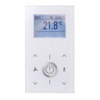
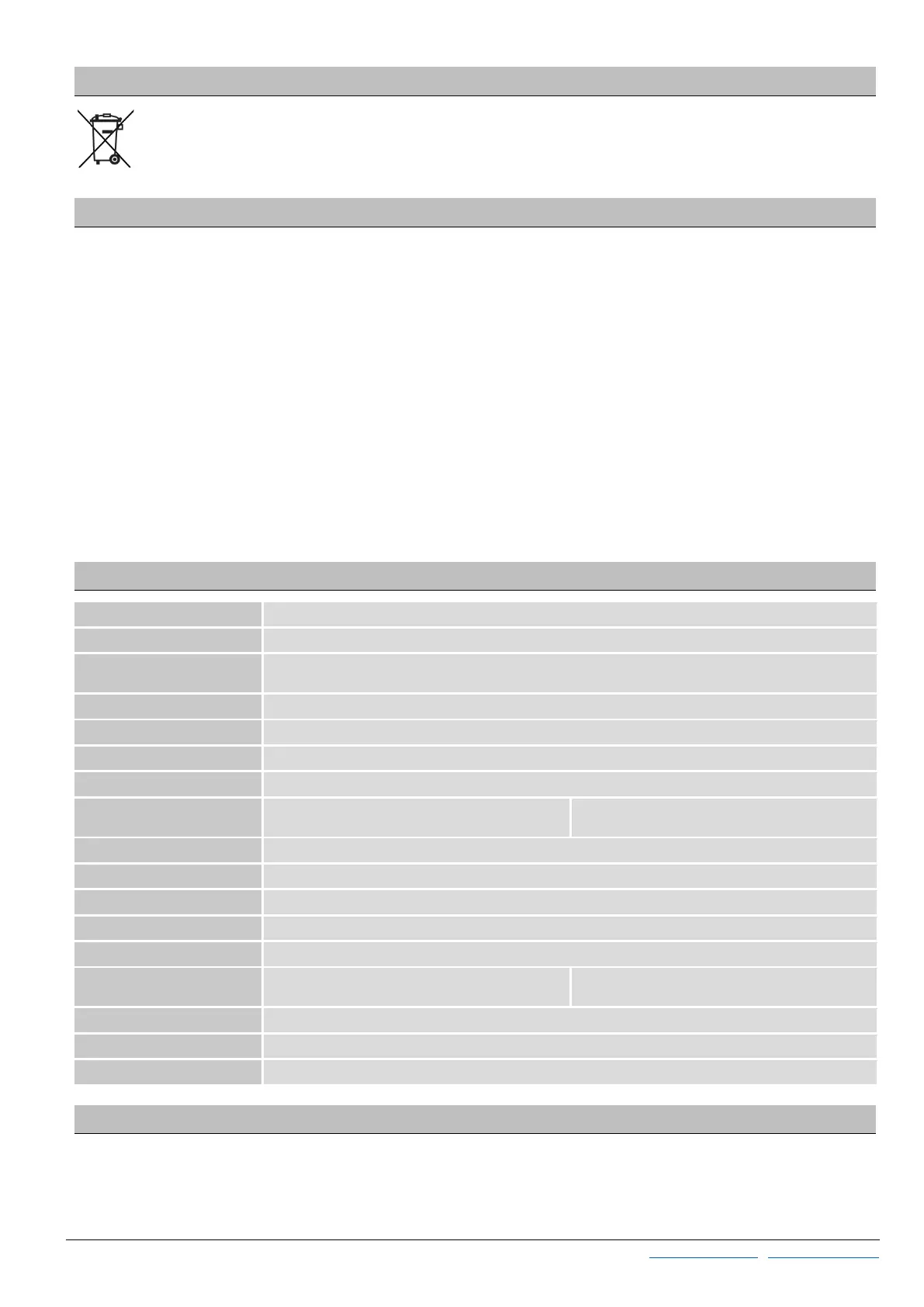
LCD 2,5“, 240x160 px, white backlighting
PC, hardened acrylic glass with high scratch resistance
IP30 according to EN 60529
Terminal 1..8
terminal block max. 1,5 mm²
Terminal 9..12
terminal block max. 1.0 mm²
0..+50 °C, max. 85% rH non-condensing
flush mounted with standard EU box (Ø=55 mm)
Diagnostics Menu
To access the diagnostics menu, select the header in the startscreen of the parameter menu, and press the ENTER key. Here
you will find various information, such as device type, software version, state of the inputs and outputs and controller state
(current manipulated variable).
 Loading...