Issue date: 24.11.2017 Page 3 / 8
Thermokon Sensortechnik GmbH, Platanenweg 1, 35756 Mittenaar, Germany · tel: +49 2778 6960-0 · fax:-400 · www.thermokon.com · email@thermokon.de
JOY_Fancoil_EC_3AO_Modbus_Datasheet_v1.6.0+_en.docx © 2017
Mounting Advices
Plasterboard boxes shall be covered by wall paper or paint to avoid that the plasterboard box's front rim will be partially visible
underneath JOY.
Maybe consider using white plasterboard boxes (i.e. Kaiser 9063-77)
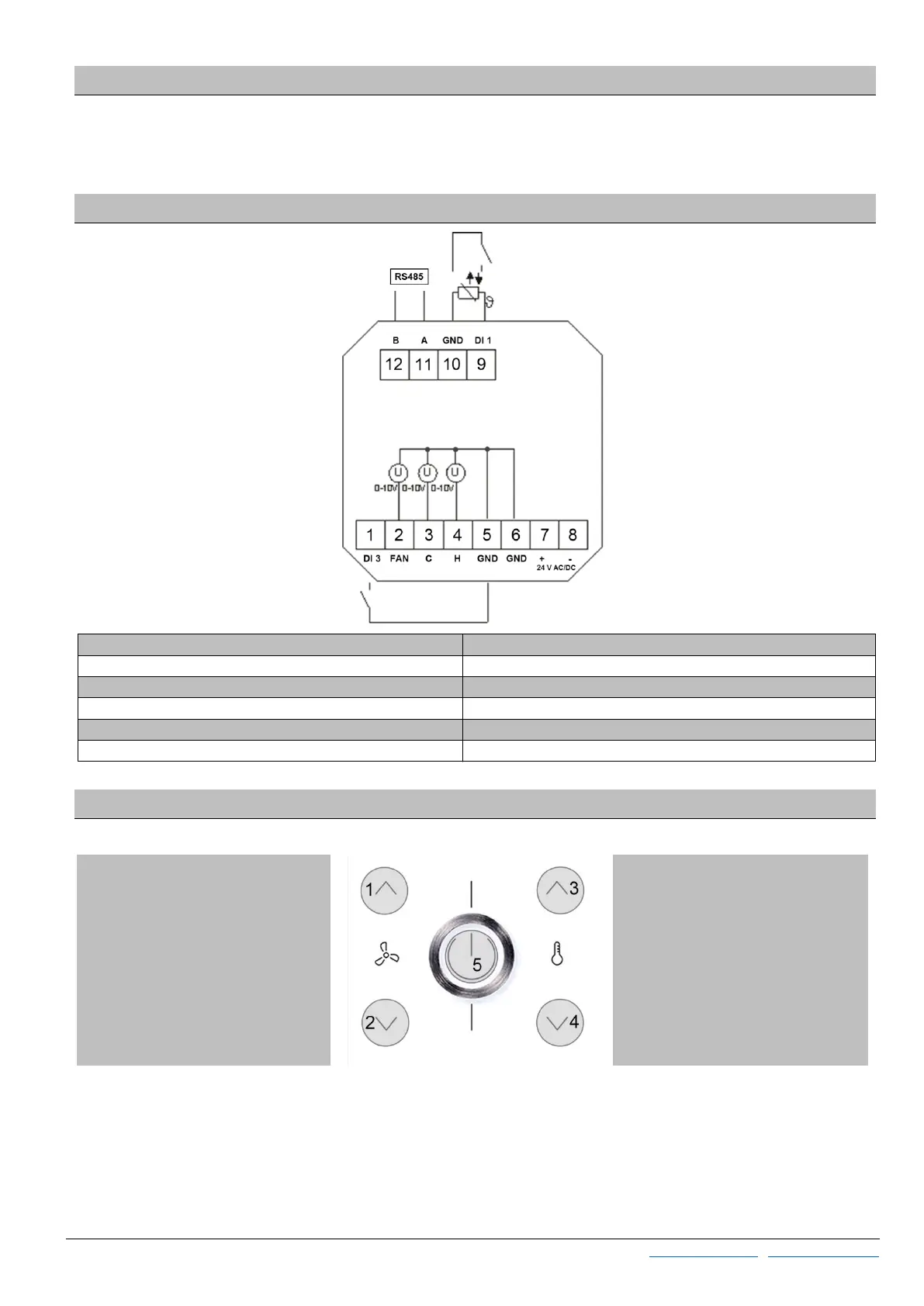
Connection Plan
1 Digital Input 3 7 24 V = (±10%) or 24 V ~ (±10%)
2 EC Fan (0..10 V) 8 -GND
3 Cooling (0..10 V) or 6-way valve 9 Digital Input 1 (or NTC10K)
4 Heating (0..10 V) or 6-way valve 10 GND DI 1
5 GND DI3 11 Modbus A
6 GND 12 Modbus B
Function Description - Buttons
On the touch surface, there are adjustment options for setpoint and fan speed regulation.
With power-button (5), the device can be set in standby mode by pressing the button (if keycard-switch is NOT used). If the
button is used as a occupancy button, the button must be pressed for at least 3s, in all other cases, a short actuation is sufficient.
In standby mode, the display and all outputs are switched off (controller deactivated). The frost and heat protection monitoring
remains active.
Modbus registers can still be read (e.g. room temperature).
The buttons (3) and (4) change
the setpoint in the range ± 3 ° C
(default setting, configurable).
The fan speed can be set by the
Buttons UP (1) and DOWN (2). 3
seconds without any interaction,
the display returns back to main
screen. While pressing of these
buttons, the white LED of the
Power-button (5) lights up for
visual feedback.
 Loading...