Do you have a question about the Thermokon NOVOS 7 and is the answer not in the manual?
Describes the intended purpose and operational environment for the device.
Outlines prohibited uses and conditions that must be avoided to prevent damage or harm.
Details the manufacturer's disclaimer for damages resulting from improper use or non-compliance.
Provides contact information for technical support and customer feedback.
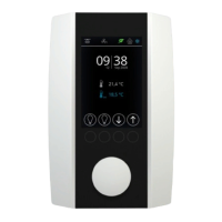
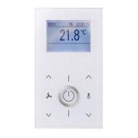
Presents the different models available within the NOVOS family and thanos EVO, highlighting design differences.
Details the physical and electrical connections required for device installation, including RS485 wiring.
Describes how to assign unique addresses to devices on the RS485 Modbus network.
Outlines the available software options (NOVOSapp, uConfig) for device parameterization.
Explains the division of device parameters into configuration and communication data blocks.
Details the user interface components for NOVOS 7 (rotary encoder, keys) and NOVOS Touch/thanos EVO (full touch).
Describes the customizable home screen, including icons, set point, and actual values.
Covers the main menu navigation for NOVOS 7 (carousel) and NOVOS Touch/thanos EVO (menu bar).
Explains the climate control functions, including set point, fan stage, ECO mode, and presence.
Details how to configure and activate up to eight individual scenes.
Describes the management of up to eight lighting groups, including switching and dimming.
Covers the control of up to eight shading circuits, including shutters, blinds, and curtains.
Provides an overview of measured values and external sensor data with traffic light indication.
Explains how to change interface parameters, date, time, and measure value offsets.
Describes how to create project-specific register structures by linking existing registers.
Details Modbus registers for room occupancy, ECO mode, setpoint, and fan stage control.
Covers coils and registers for controlling lighting circuits, including status, dimming, and color.
Details Modbus registers for controlling shading elements like blinds, shutters, and curtains.
Explains registers for status reports, display settings, LED control, and piezo buzzer functions.
Lists Modbus registers for internal and external sensor measurements and error status.
Covers device description, production dates, operating hours, and firmware versions.
Details settings for measuring unit, language, date/time formats, and button behavior.
Covers settings for screen brightness, standby behavior, screensaver, colors, and lockscreen.
Details parameters for climate control, including temperature display, setpoint, ECO button, and room occupancy.
Describes configuration options for lighting menus, number of circuits, and icon selection.
Covers configuration for shading menus, number of circuits, and graphical representation.
Details settings for the scene menu, including number of scenes and icon selection for each scene.
Lists address ranges and units for various measured variables like temperature, humidity, CO2, and VOC.
Defines configuration parameters for creating custom favorite button assignments.
Details coils for lighting status, including ON/OFF control for individual lighting circuits.
Describes coils for scene status, indicating whether a scene is active or not.
Lists coils for controlling the visibility of various icons on the display, such as Dew point or ECO.
Covers coils for enabling AUTO mode for lighting circuits, disabling manual button control.
Details coils for enabling AUTO mode for shading circuits, disabling manual button control.
Explains the integrated calendar function for automated, time-controlled actions and register value changes.
Lists the MODBUS control commands supported by the device, such as Read Holding Register.
Explains the Master/Slave protocol and the structure of data frames used in MODBUS communication.
Details the RTU transmission mode, telegram structure, and CRC checksum calculation for data integrity.
| Display | LCD |
|---|---|
| Power Supply | 24 V AC/DC |
| Enclosure Material | Plastic |
| Protection Class | IP30 |
| Mounting | Wall mounting |
| Terminals | Screw terminals |
| Device Type | Room thermostat |
| Operating Temperature Range | 0..+50 °C |
| Storage Temperature Range | -20°C to 60°C |
| Humidity Range | 0% to 95% RH (non-condensing) |
| Sensor | Temperature sensor |
| Measuring Range Temperature | 0..+50 °C |
| Accuracy Temperature | ±0.5°C |
| Output | Relay |
| Ambient Temperature | 0..+50 °C |
| Weight | Approx. 120 g |
| Control Range | 5°C to 30°C |