Do you have a question about the Thermokon JOY Fancoil EC 3AO RS485 Modbus and is the answer not in the manual?
| Brand | Thermokon |
|---|---|
| Model | JOY Fancoil EC 3AO RS485 Modbus |
| Category | Thermostat |
| Language | English |
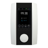
Modern flush-mounting fan coil thermostat with 2.5" LCD, touch-sensitive surface, and 3 time program options.
Installation and assembly of electrical equipment must be done by authorized personnel only.
Proper mounting location is crucial for accurate room temperature measurement and depends on wall dynamics.
Wall material and mounting type (flush vs. surface) affect sensor response time to thermal variations.
Key measured parameters include temperature and Modbus network settings.
Supports RS485 Modbus with configurable baud rates and parity options.
Provides 0-10V output for EC Fan control, heating/cooling, or 6-way valve control.
Operates on 24V DC (±10%) or 24V AC (±10%) SELV.
Achieves ±1 K accuracy typically at 21 °C.
Supports digital inputs for NTC10K sensors or floating contacts.
Features a PC enclosure with hardened acrylic glass, rated IP30.
Operates within 0–50 °C and max. 85% rH non-condensing.
Cover plasterboard box rims with wallpaper or paint; consider white boxes for better integration.
Terminal 1 is assigned to Digital Input 3.
Terminal 2 provides 0-10V output for EC fan control.
Terminals 3 and 4 are used for 0-10V cooling or 6-way valve control.
Terminals 3 and 4 are also used for 0-10V heating or 6-way valve control.
Terminals 5 and 6 are ground connections for DI3 and general use.
Terminals 7 and 8 are for 24V AC/DC power supply.
Terminal 8 provides a ground connection.
Terminal 9 accepts Digital Input 1 or an NTC10K sensor.
Terminal 10 is a ground connection for Digital Input 1.
Terminal 11 is for Modbus communication (A).
Terminal 12 is for Modbus communication (B).
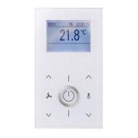
Fan speed is adjusted using UP (1) and DOWN (2) buttons; white LED indicates status.
Buttons (3) and (4) adjust the setpoint within a configurable range, typically ±3°C.
Power button (5) activates standby mode, switching off display and outputs; frost protection remains active.
The thermostat utilizes a PI controller for heating and cooling with configurable 6-way valve control.
Fan speed is linked to controller output in automatic mode; manual override is possible.
0-10V fan control is proportional to the PI controller's calculated manipulated variable.
Up to 5 fan stages can be set, linearly divided to the 0-100% manipulated variable.
PI control loop time response depends on proportional (Xp) and integral (Tn) parameters.
Proportional band (Xp) influences control action strength and oscillation tendency.
Integral time (Tn) determines how the integral component affects control deviation.
Defines fixed minimum or maximum values for the actuating variable.
Displays internal sensor value or external sensor value if configured.
Displays current date, time, and ECO-mode status.
Shows heating/cooling mode, occupancy, and window contact status.
Icons indicate occupancy, window contact, heating/cooling, fan speed, and active time channel.
Configuration menu is activated by pressing 'up', 'left', and 'right' buttons simultaneously for 3 seconds.
Navigate menus using 'up', 'down', 'left', 'right' buttons; submenus accessed with 'right'.
Set point and timer via three prioritized time channels, each with four periods.
Adjustable dead zone for ECO-mode optimizes comfort and energy saving.
Configuration menu accessed by pressing 'up' and 'down' buttons simultaneously for 5 seconds.
Adjustable Modbus address range from 1 to 247.
Supports baud rates of 9600, 19200, 38400, and 57600 Bd.
Configurable parity options include None, Odd, and Even.
Allows connection of an external sensor (NTC10K) for thermostat control.
Input for switching between heating and cooling modes based on contact state.
Automatic mode switching between heating and cooling based on temperature thresholds.
Window contact input switches to setback set point (Heat/Cool SP).
Active dewpoint contact locks the cooling controller.
Occupancy status adjusts heating/cooling set points; symbol displayed when active.
Keycard-switch locks operation, turns off display, and sets to 'unoccupied' state.
SD cards facilitate firmware updates and device configuration uploads.
Integrated bootloader allows application updates via SD card.
Display, set point, controller, and 6-way valve outputs configured via software.
Provides overall dimensions of the thermostat unit in millimeters.
Optional accessory for RS485 Modbus conversion to USB.