Appendix F ’Network Settings (6RU and 10RU Devices)’ — Redundancy Schemes
258 ViBE VS7000
User Manual
Redundancy Schemes
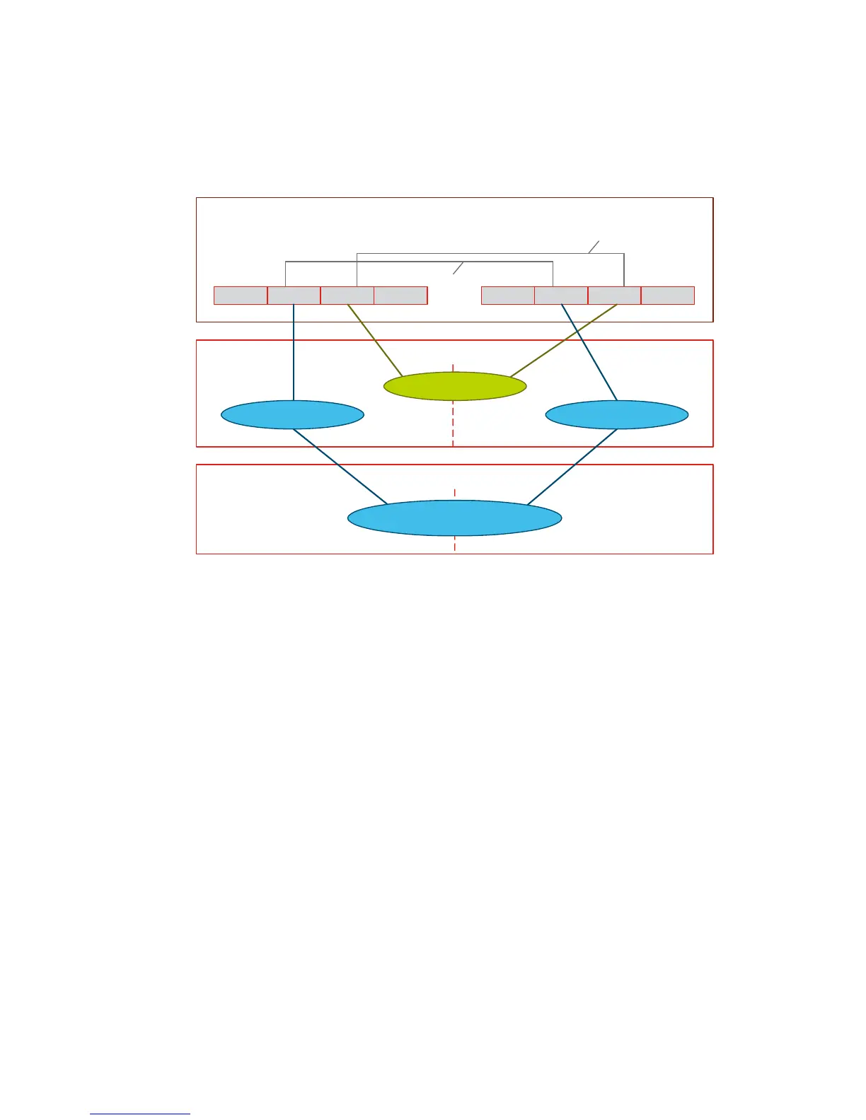
Figure F-1. Redundancy scheme for an internal network or an external network
Internal LAN
An internal LAN must be configured on the two Flex10.
The two interfaces of a blade bond are connected to this same LAN.
Redundancy is thus ensured if:
An interface of a blade is faulty.
A Flex10 is faulty.
External LAN
At the Flex10 level, an external LAN is divided into two LANs: one being
on the first Flex10 and the other one on the second Flex10.
One interface of a blade bond is connected to one of the 2 LANs, the other
one being connected to the other LAN.
These 2 LANs are configured in SmartLink, i.e. if a LAN looses its external
interface (link down of an external connector), the link down is "sent" to
the internal interfaces of this LAN, and thus to the blades, which causes
to switch the bonds on the other Flex10.
FlexNIC 1 FlexNIC 2 FlexNIC 3 FlexNIC 4 FlexNIC 5 FlexNIC 6 FlexNIC 7 FlexNIC 8
pNIC 1 pNIC 2
BLADE CENTER
Flex10
External LAN-A External LAN-B
1 or 2 switches
External LAN
bond 2
bond 3
Internal LAN
Flex10 A Flex10 B
 Loading...