Page 14 18728-D01
Single- and Dual-Axis Scanning Galvo Systems for Small Beam Diameters
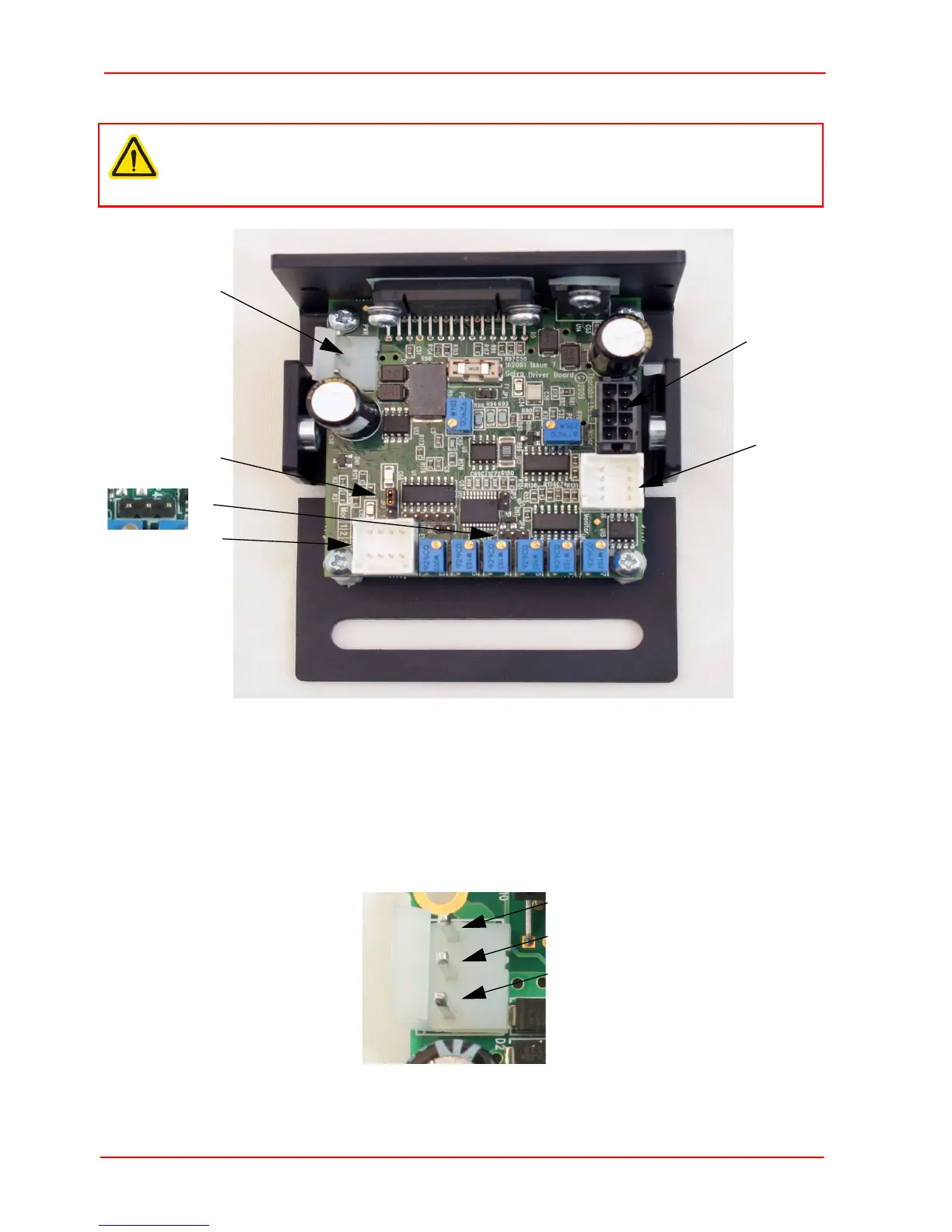
3.3.3 Electrical Connections
Fig. 3.12 Connector Identification
1) Identify connector J10 on each driver board, and make power connections as
shown below. Thorlabs supply a suitable PSU (GPS011) for powering a single or
dual axis system (see Section 3.3.1.). A bare cable, crimp connectors (Molex Pt
No 2478) and housings for use with general lab PSUs is supplied with each driver
board.
Fig. 3.13 J10 Power Connector Pin Identification
Caution
During the electrical installation, cables should be routed such that power and
signal cables are separated so that electrical noise pick up is minimized.
 Loading...