Page 20 18728-D01
Single- and Dual-Axis Scanning Galvo Systems for Small Beam Diameters
4.4 Recommended Scanning Angles
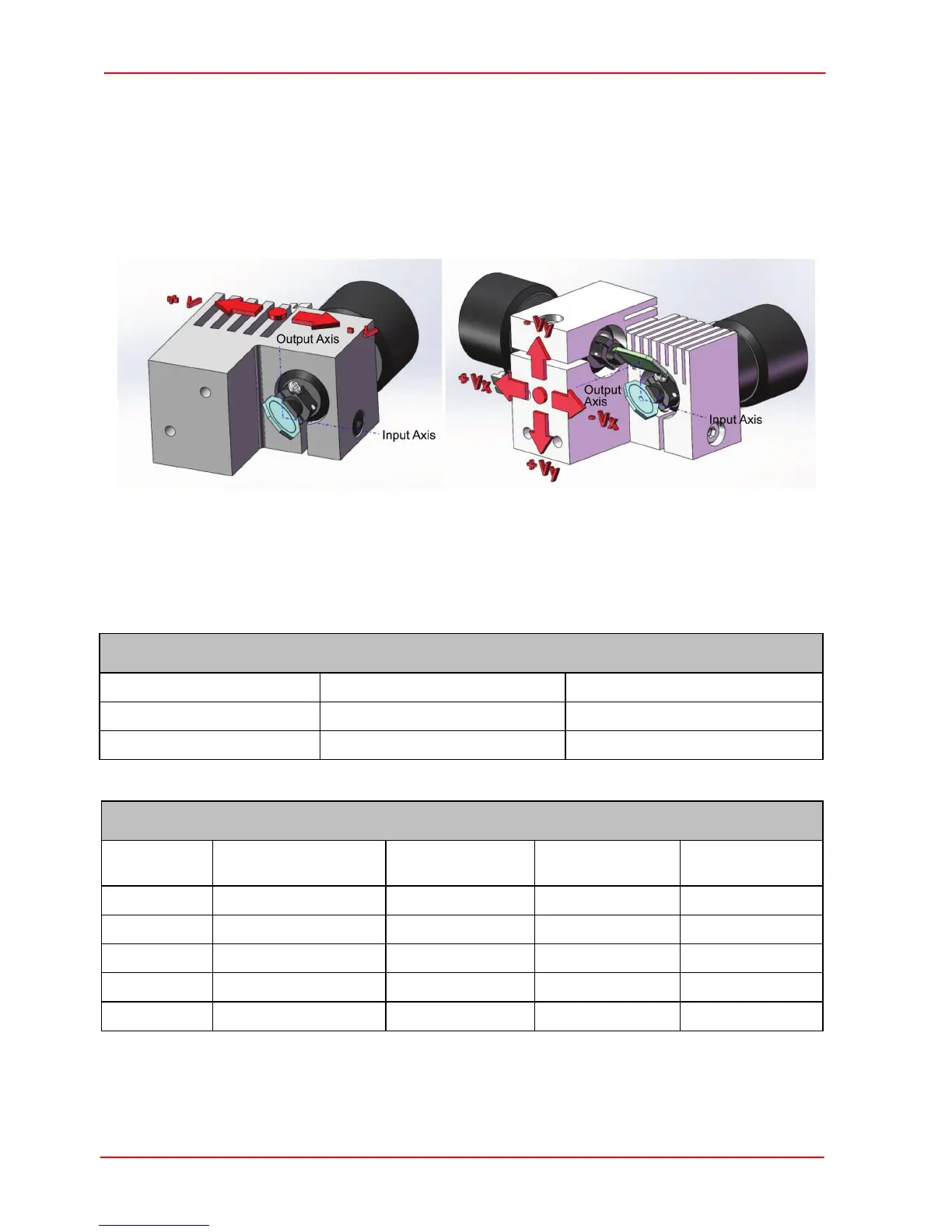
The ideal scanning angle is dependent upon a number of conditions. Firstly, the larger
the diameter of the input laser beam, the smaller the achievable scanning angle.
Secondly, the applied input voltage causes the laser beam to move away from the
center of the mirrors. The larger the input voltage then the greater the movement from
the center, as shown below.
Lastly, on dual-axis systems, there is an offset alignment between the X and Y axis
mirrors that also limits the scan angle.
The table below gives recommended scanning angles for various beam diameters.
GVS001, GVS101, GVS201 and GVS301,
Input Beam Diameter Mechanical Scan Angle Optical Scan Angle
4 mm and less ± 12.5° ± 25°
5 mm + 10°, -12.5° + 20°, -25°
GVS002, GVS102, GVS202 and GVS302,
Input Beam
Diameter
Mechanical
Scan Angle X
Optical
Scan Angle X
Mechanical
Scan Angle Y
Optical
Scan Angle Y
1 mm + 11.0°, - 12.5° + 22.0°, - 25° ± 12.5° ± 25°
2 mm + 10°, - 11.5° + 20°, - 23° ± 12.5° ± 25°
3 mm + 9.5°, - 10° + 19°, - 20° ± 12.5° ± 25°
4 mm ± 8.5° ± 17° ± 12.5° ± 25°
5 mm ± 8° ± 16° + 12.5°, -3° + 25, -6°