Page 18 18728-D01
Single- and Dual-Axis Scanning Galvo Systems for Small Beam Diameters
3.3.4 Diagnostic Signal Descriptions
Scanner Position - This signal is proprotional to the position of the scanner mirror, with
a scaling of 0.5 Volts per degree of mechanical movement.
Internal Command Signal - The command signal following amplification by the input
stage. The scaling is 0.5 Volt per degree of mechanical movement.
Positioning Error x 5 - This signal is proportional to the difference between the
demanded and the actual positions - (Position - Command) x 5 (i.e. (Pin 1 - pin 2) x 5).
Motor Drive Current - The drive current of the motor (2V per A), i.e. if drive signal is
2V, the drive current is 1 A.
Motor + Coil Voltage /2 - This pin outputs the drive voltage to the “+” side of the motor coil.
It is scaled down by a factor of 2. The drive voltage determines the current, which then
determines the acceleration. It is not required if the user only wants to monitor position.
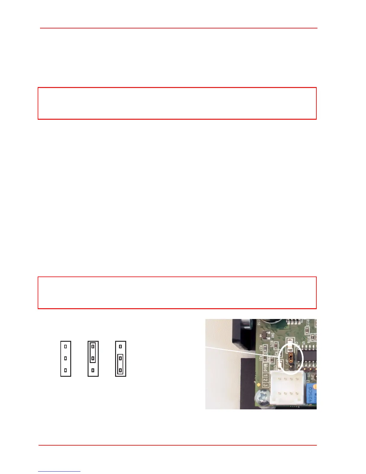
3.3.5 Setting the Volts/Degree Scaling Factor
Servo driver cards manufactured after October 2015 have a jumper which is used to
set the Volts per Degree scaling factor. The cards are shipped with the scaling set to
0.8 V/°, where the max scan angle is ±12.5°, and is compatible with driver cards
manufactured before October 2009. To set the scaling factor to 1 V/° and the
maximum scan angle to ±10°, proceed as follows:
1) Identify JP7 as shown in Fig. 3.18.
2) Set the jumper position for the corresponding scaling factor as shown below.
Fig. 3.18 Setting the Volts/Degree Scaling Factor
Note
The Scanner Position and Internal Command signals are scaled internally by the
driver circuit and are essentially equivalent to the input signal /2.
Note
The 0.5V/° scaling factor is provided to allow the full scan angle to be achieved using
small input signals. In this case, the input voltage should be limited to ±6.25 V max
 Loading...