Rev 22 Feb 2019
Page 3
Chapter 1 Overview
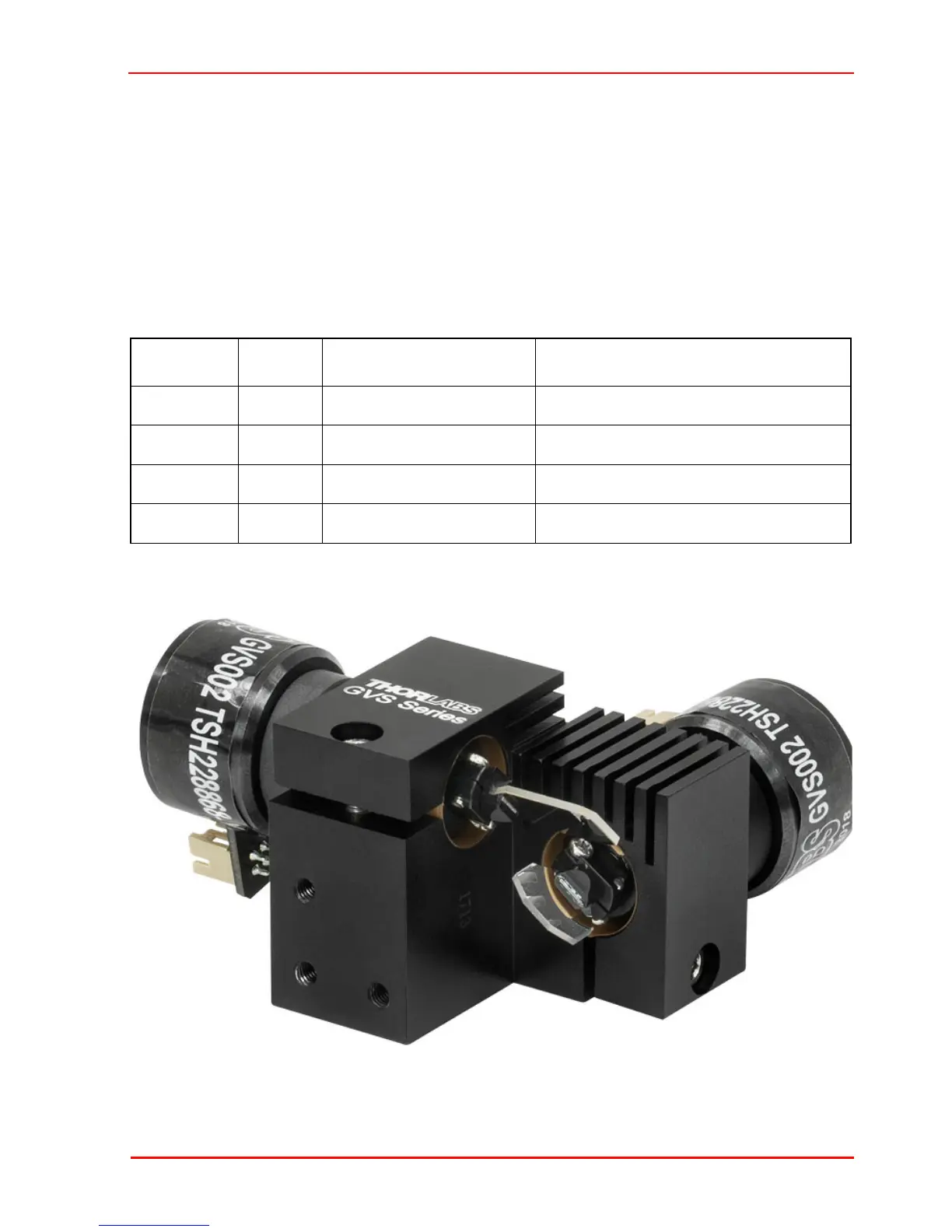
1.2.3 The Mirror
The mirror assembly is attached to the end of the actuator, and deflects the light beam
over the angular range of the motor shaft. Scanning galvo applications demand high
speed and frequencies of the shaft rotation, and so the inertia of the actuator and
mirror assembly can have a profound effect on the performance of the system. High
resonant frequencies and enhanced stiffness in the mirror assembly also add to
system performance by increasing bandwidth and response times.
Wavelength ranges and damage threshold of the different mirror coatings are details
below:
Fig. 1.3 Mirror Assembly Detail
Part No Coating Wavelength Damage Threshold
GVS00x Silver 500 nm - 2.0 µm
3 J/cm
2
at 1064 nm, 10 ns pulse
GVS10x Gold 800 nm - 20.0 µm
2 J/cm
2
at 1064 nm, 10 ns pulse
GVS20x E02 400 nm - 750 nm
0.25 J/cm
2
at 532 nm, 10 ns pulse
GVS30x K13 532 nm and 1064 nm
5 J/cm
2
at 1064 nm, 10 ns pulse
 Loading...