Page 10 ETN037435-D02
LSS10 LED Light Box
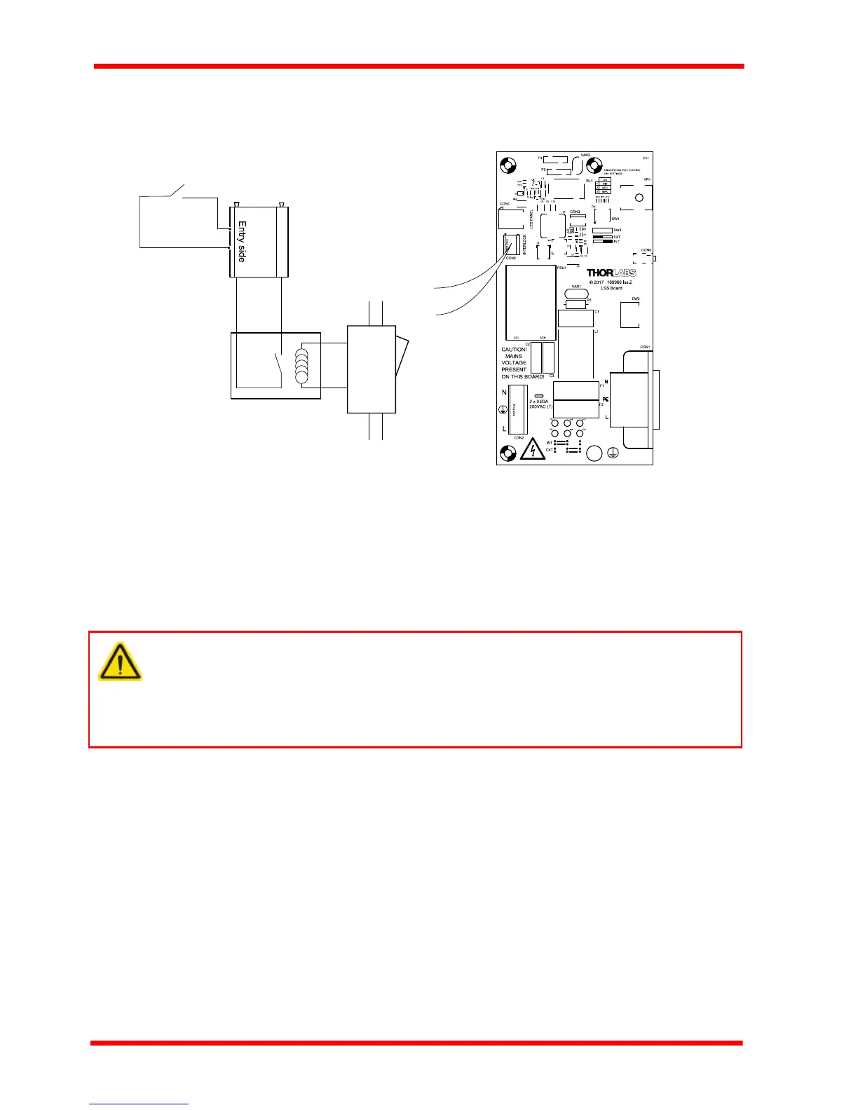
Internal connection is achieved by hard-wiring to the terminal block provided on the
PCB as shown in Fig. 4.3.
Fig. 4.3 PCB interlock wiring
The ON/OFF switch on the panel controls power to the interlock relay, and completes
the interlock circuit when the switched ON.
4.3 Replacing the Internal Fuses
In case of an internal fuse blow, the fuse should be replaced as follows:
1) Remove power from the unit.
2) Remove the front panel - see Fig. 3.2.
3) Locate the broken fuse - see Fig. 3.3
4) Replace the fuse with another of the same type, 0.63A (T) 250 VAC.
5) Refit the front panel.
Warning
The unit uses mains voltages. This is hazardous and can cause serious injury.
The fuses must be replaced only by suitably trained and qualified personnel
who understand the hazards associated with using high voltages and the steps
necessary to minimize the risk of electrical shock.
INTERLOCK
CON6
laser external
interlock circuit
interlock
relay
lightbox
panel
switch
 Loading...