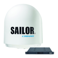
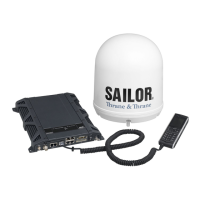
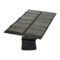
The SAILOR 900 VSAT is a sophisticated satellite communication system designed for maritime use, providing reliable broadband connectivity at sea. This quick guide and user manual offer essential information for its setup, configuration, and ongoing operation, ensuring users can effectively manage their satellite communication needs.
Function Description
The SAILOR 900 VSAT system is pre-configured during installation with all necessary satellite and modem profiles, enabling immediate operation upon startup. It automatically defaults to the last selected satellite profile, streamlining the process of establishing communication. The core function of the system is to provide continuous, high-speed internet access, voice communication, and other data services to vessels, regardless of their location. This is achieved through its ability to track and connect to geostationary satellites, maintaining a stable link even in dynamic maritime environments.
The system's Antenna Control Unit (ACU) is the central hub for managing the VSAT operations. It houses the intelligence for antenna pointing, satellite acquisition, and overall system health monitoring. The ACU is equipped with a built-in web interface, which serves as the primary tool for advanced configuration, parameter adjustments, and detailed system diagnostics. This web interface allows users to switch between different satellite or modem profiles, fine-tune antenna parameters, and monitor various aspects of the system's performance.
Key components of the system include the antenna, which physically tracks and communicates with satellites, and the modem, which processes the satellite signals for data transmission and reception. The ACU orchestrates the interaction between these components, ensuring optimal performance. The system is designed to be robust and reliable, capable of operating in challenging marine conditions, providing critical communication links for navigation, crew welfare, operational efficiency, and safety.
Usage Features
The SAILOR 900 VSAT offers a range of user-friendly features designed to simplify its operation and management.
Initial Setup and Configuration:
- Power On: The system is activated by switching on the SAILOR 900 VSAT at the power switch of the ACU. This initiates the system's boot-up sequence.
- PC Connection: For configuration and detailed monitoring, a PC needs to be connected to LAN port 3 of the ACU (or the Front LAN connector for rack versions) using a straight Ethernet cable. This establishes a direct communication link between the PC and the ACU's web interface.
- Web Interface Access: Users access the built-in web interface by entering the default IP address,
http://192.168.0.1, into their Internet browser. This immediately opens the DASHBOARD, providing an overview of the system's status.
- Satellite Profile Activation: From the DASHBOARD, users can navigate to the SETTINGS section to activate a new satellite profile. This is crucial when changing operational regions or service providers, ensuring the system connects to the appropriate satellite.
Navigation and Parameter Viewing (via ACU Keypad):
The ACU features a keypad with arrow keys and an OK button, allowing users to navigate through various menus and view system parameters directly on the ACU's display.
- Menu Navigation: Use the arrow keys to scroll through the available menus, such as MAIN, ANT, MODEM, NET, SAT, and EVENT.
- Parameter Selection: Press OK to enter a menu, then use the arrow keys to select specific parameters for viewing. The current menu name is always displayed in the upper left corner of the screen.
- Key Parameters Viewable:
- MAIN: Displays general status information like Power, Logon, Fail/Pass, current satellite, TX status, GPS status, Heading status, and LAN status.
- ANT (Antenna): Provides details on antenna pointing (elevation, azimuth), polarization, GPS status, heading, software versions, and serial numbers.
- MODEM: Shows modem type, TX enable status, RX lock status, and signal level.
- NET (Network): Displays IP addresses and masks for various LAN ports (1/2, 3, 4) and the default gateway.
- SAT (Satellite): Offers information on satellite position, RX/TX polarization, RX/TX frequencies, LNB LO, and BUC LO.
- EVENT: Lists recent system events, providing a chronological log of operations and potential issues.
Web Interface (Thrane & Thrane Interface):
The web interface provides a comprehensive and graphical way to manage the SAILOR 900 VSAT.
- DASHBOARD: Offers an immediate overview of the system's operational status.
- SETTINGS: Allows configuration of Satellite Profiles, VSAT Modem Profiles, Blocking Zones, Network settings, E-Mail Setup, Reports, and Dual Antenna configurations. This is where users can switch between different operational modes and fine-tune network parameters.
- SERVICE: Provides tools for Uploads, Calibration, Line Up, Dual Antenna Mode management, and XIM Data access. These features are often used for diagnostics, maintenance, and performance optimization.
- ADMINISTRATION: Manages User Permissions, Export/Import Config, and Factory Default settings. This section is crucial for system administrators to control access and manage system configurations.
- HELPDESK: Contains the Event List and Self Test functions, aiding in troubleshooting and system diagnostics.
- SITE MAP: Provides a hierarchical overview of all available sections within the web interface, making navigation easier.
Maintenance Features
The SAILOR 900 VSAT incorporates several features to facilitate maintenance, troubleshooting, and ensure long-term reliability.
Resetting the ACU:
In cases where the ACU might become unresponsive or require a hard reset, a simple procedure is available:
- Initiate Reset: Press and hold both the arrow up and down keys on the ACU keypad simultaneously.
- Display Shutdown and Reboot: Continue holding the keys until the ACU display shuts down, indicating the system is rebooting.
- System Reinitialization: Wait for the system to fully reboot and become operational again. Upon reboot, the ACU will automatically select the last active satellite profile, restoring normal operation.
Diagnostics and Monitoring:
- Event List (HELPDESK): Both the ACU keypad interface and the web interface provide access to an event log. This log records system events, warnings, and errors, which are invaluable for diagnosing issues and understanding system behavior over time.
- Self Test (HELPDESK): The web interface includes a self-test function that allows users to run diagnostic checks on various components of the VSAT system. This helps in identifying potential hardware or software problems before they escalate.
- Reports (SETTINGS): The web interface can generate reports on system performance, usage, and other operational data. These reports can be used for performance analysis, capacity planning, and identifying trends that might indicate a need for maintenance or adjustments.
- Signal Level Monitoring: The MODEM menu (via ACU keypad) and the web interface display the signal level, which is a critical indicator of the quality of the satellite link. A drop in signal level can indicate antenna pointing issues, weather interference, or problems with the satellite transponder.
- Firmware Updates: While not explicitly detailed as a user-initiated feature in the quick guide, the "Upload" function under the SERVICE menu in the web interface suggests the capability to upload new firmware or configuration files, which is a common maintenance task for improving system performance, adding new features, or fixing bugs.
- Export/Import Config (ADMINISTRATION): This feature allows administrators to save the current system configuration and restore it later. This is crucial for backup purposes, especially before major changes or in case of system recovery, ensuring that the system can be quickly brought back to a known working state.
- Factory Default (ADMINISTRATION): The option to restore factory default settings is a powerful maintenance tool. It can be used to revert all configurations to their original state, which is often necessary when troubleshooting complex configuration issues or preparing the system for a new installation.
Documentation:
For comprehensive maintenance and troubleshooting, the quick guide repeatedly refers to the "SAILOR 900 VSAT Installation & user manual." This detailed manual would contain in-depth instructions for advanced diagnostics, component replacement, and other maintenance procedures not covered in the quick guide.
The SAILOR 900 VSAT is designed with both ease of use and robust maintenance capabilities in mind, ensuring reliable communication for maritime operations.