Thunder Heart Performance Corp. 615-672-8811 www.thunder-heart.com
4 EI4250
1.3 Connector Assembly
The following information highlights proper assembly procedures for the AMP
connectors included with the Micro Harness Controller system:
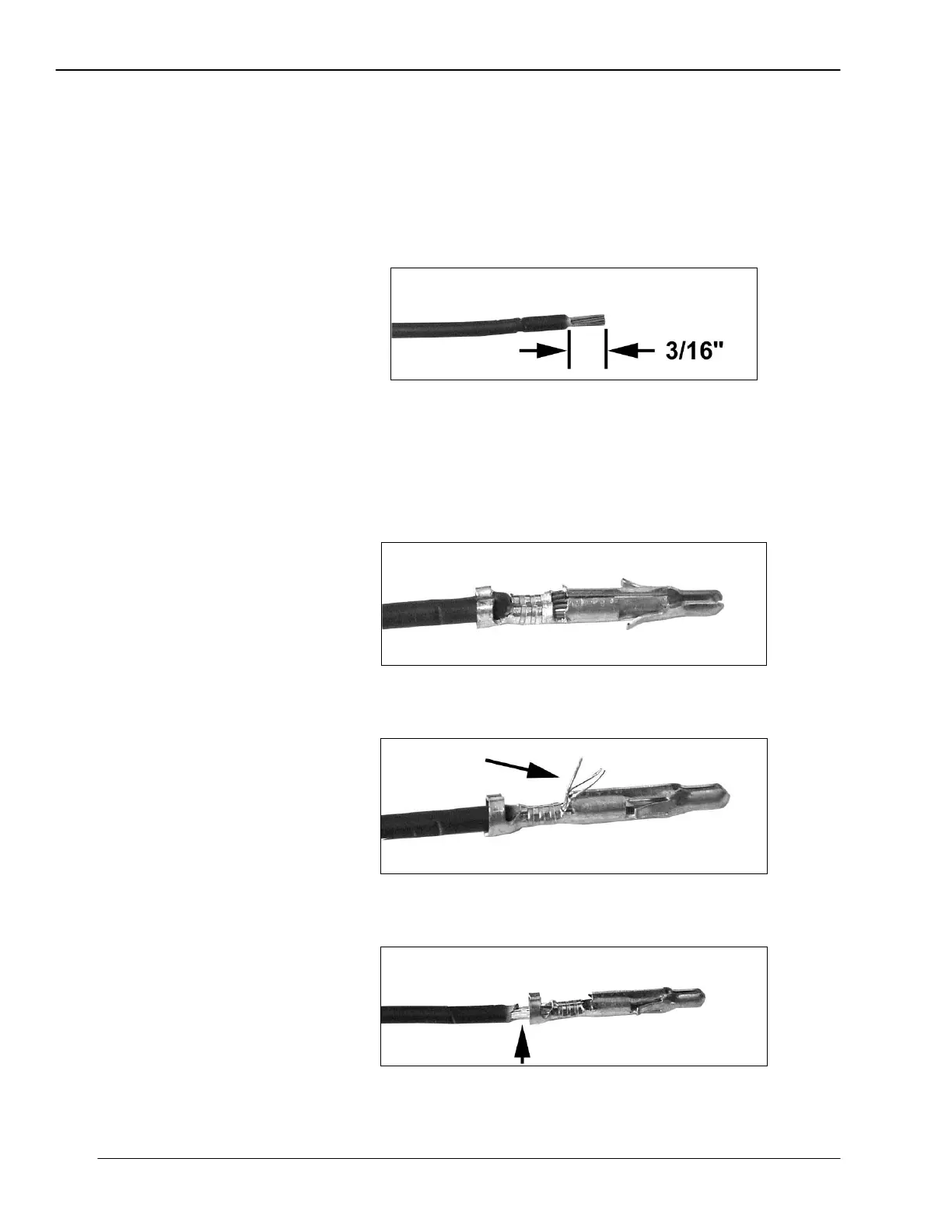
1. Strip approximately 3/16” of insulation off of the end of the wire to be
terminated.
Figure 5—Proper wire strip amount
2. Clip a terminal from the supplied “tree” of terminals.
3. Using either a “W” or an “AMP” tool, crimp the terminal onto the end of
the wire. The following figures show examples of “good” and “bad”
crimps:
Figure 6—Good Crimp; insulation retained by outside tabs, conductor
retained by inside tabs
Figure 7—Bad Crimp; too much wire stripped; strands exposed outside
of terminal
Figure 8—Bad Crimp; too much wire stripped; insulation not retained
by outside tabs