10
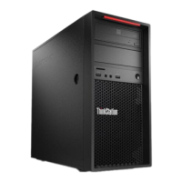
3. Connect the SATA signal and power cables to the connector on the rear of the FLEX
module.
4. Install the Thunderbolt 3 PCIe x4 card in the appropriate slot, as designated by the
following table:
P520c: PCIe slot 4
P520: PCIe slot 6
P720: Primary choice: PCIe slot 2; Secondary choice: slot 1
P920: Primary choice: PCIe slot 2; Secondary choice: slot 4
5. Route and connect the 3 cables that extend from the rear of the FLEX module
Cable routing: this will vary depending on the particular workstation and the currently
installed system components. However, typically the cables should be routed from the
rear of the FLEX module toward the bottom of the workstation, passing directly behind
the front system fan, to an area near the PCIe slots.
Cable connections:
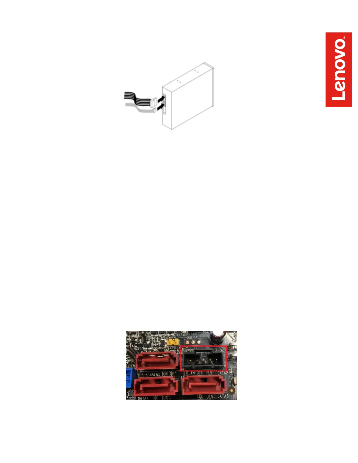
- GPIO cable: connected to a black, 5-pin connector that is located along the bottom
edge of the motherboard (when viewed from the side of the workstation). The precise
connector location varies across the four workstations covered in this guide, but it is
in the general vicinity of the SATA connectors and looks like this: