2007.03.07 Flow2 stairlift Tab 04: Install, adjust and release
www.ThyssenKruppAccessibility.nl 21
Assembly
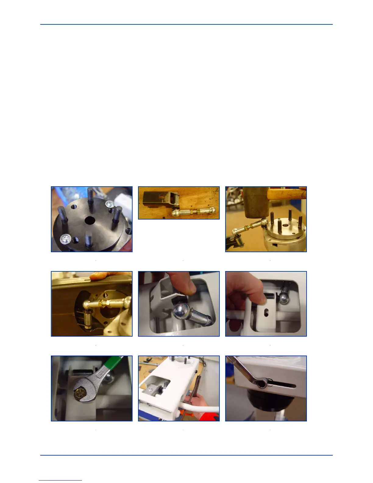
Fitting manual swivel seat
1. Remove the standard screws and the seat screw from the squeeze unit flange and position the
4 threaded ends of the squeeze unit over the swivel adjustment unit, see Fig. 3-19.
2. Remove the ball head assembly from the adjustment unit, see Fig. 3-20.
3. Screw the ball head to the squeeze unit on the opposite side to the swivel side. Click the ball
head onto the piston. Using the locking pins, see Fig. 3-21.
4. Slide the ball with holder into the sleeve and screw the swivel frame tightly to the squeeze unit,
see Fig. 3-22.
5. Fit the box on the piston, see Fig. 3-23. Attach the holder to the lever, see Fig. 3-24 and Fig. 3-
25.
6. Check that the box is in line with the leg, see Fig. 3-26.
7. Adjust the buffers, see Fig. 3-27.
8. Go to step 1 of Section 3.6
Fig. 3-19 Threaded ends on
swivel
1
Fig. 3-20 Ball head assembly Fig. 3-21 Ball head on piston
1
Fig. 3-22 Ball holder in frame
1
Fig. 3-23 Position the piston
1
Fig. 3-24 Attach piston mounting
1
Fig. 3-25 Secure piston mounting
1
Fig. 3-26 Alignment
1
Fig. 3-27 Adjusting the buffers
1