APPENDIX
139
NA10 - Manual - 04 - 2022
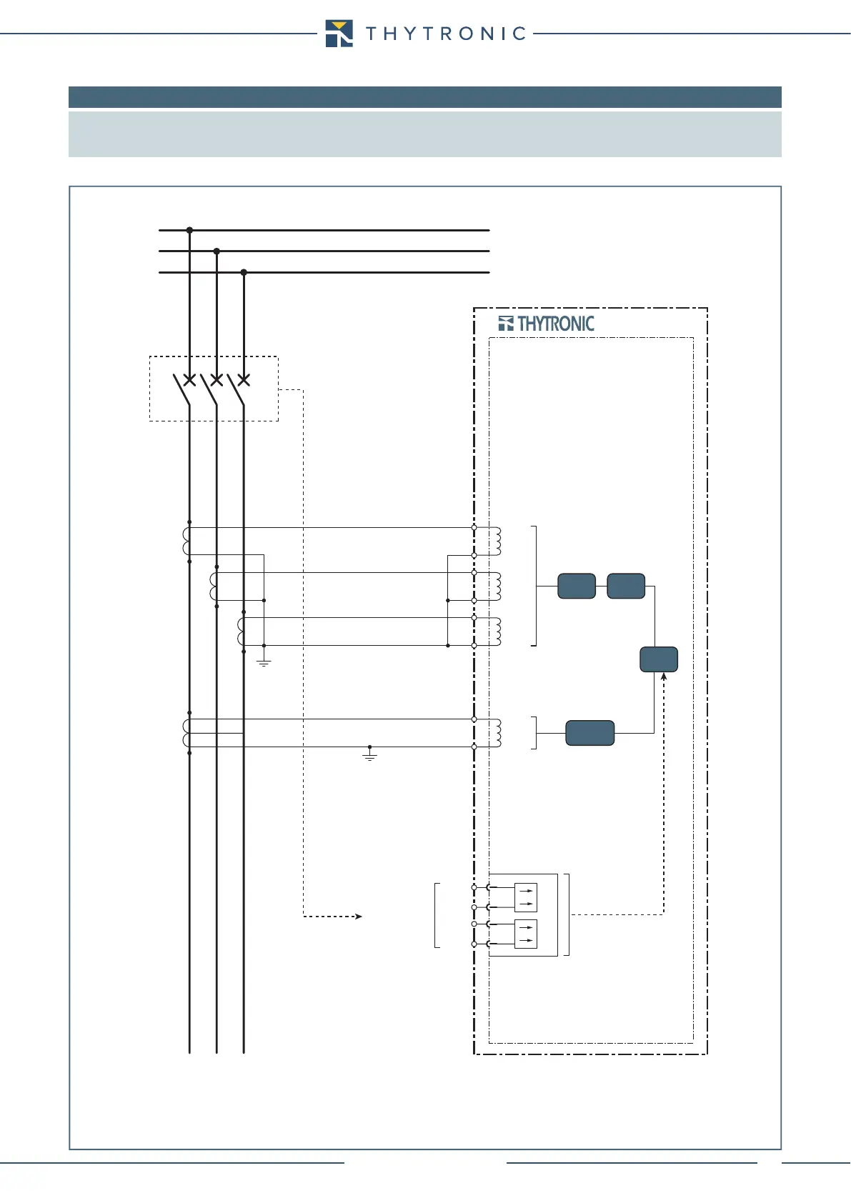
8.6 APPENDIX B3 - Connection diagrams
Note: Some typical connection diagram are shown.
All diagram must be considered just as example; they cannot be comprehensive for real applications.
For all diagrams the output contacts are shown in de-energized state for standard reference.
CB position
NA10-SCH.ai
NA10
L1
L2
L3
C2
C1
C3
C4
C5
C6
P1
S1
S2
P2
I
L1
I
L2
I
L3
I
E
C7
C8
P1
S1
S2
P2
50N/51N
50/51
74CT
50BF
BINARY INPUTS
A19
IN1
IN2
A20
A21
A22
Three phase CTs and residual current from core balanced CT

 Loading...


