FUNCTION CHARACTERISTICS
46
NA10 - Manual - 04 - 2022
The second overcurrent element can be programmed with definite or inverse time characteristic
by setting the I> Time characteristic (I>>Curve) parameter (DEFINITE, I2t) available inside the
Set \ Profile A(or B) \ Phase overcurrent-50/51\ I>> Element \ Setpoints menu.
The trip of I> element may be inhibited by the start of the second and/or third element (I>>, I>>>) by set-
ting ON the Disable I> by start I>>, Disable I>> by start I>>> (I>disbyI>>, I>disbyI>>>) parameters
available inside the Set \ Profile A(or B) \ Phase overcurrent-50/51 \ I>> Element (I>>> Element) \Setpoints
menus.
Similarly the trip of the I>> element may be inhibited by start of the third element (I>>>) by setting ON
the Disable I>> by start I>>> (I>>disbyI>>>) parameter available inside the Set \ Profile A(or B)
\ Phase overcurrent-50/51\I>>> Element \ Setpoints menu.
All the parameters can be set separately for Profile A and Profile B (Set \Profile A(or B)\Phase over-
current-50/51 \ I> Element (I>> Element, I>>> Element) \Setpoints menus).
An adjustable reset time delay is provided for every threshold (t
>RES
, t
>>RES
, t
>>>RES
).
Each overcurrent element can produce the Breaker Failure output if the I> BF, I>> BF and/or
I>>> BF parameters are set to ON. The parameters are available inside the Set \ Profile A(or B) \
Phase overcurrent-50/51 \ I> Element (I>> Element, I>>> Element) \ Setpoints menus.
[1]
For all overcurrent elements, a block from the second harmonic restraint may be set by set-
ting ON the I>2ndh-REST, I>>2ndh-REST, I>>>2ndh-REST parameters inside the
Set \ Profile A(or B) \ Phase overcurrent-50/51 \ I> Element (I>> Element, I>>> Element) \ Setpoints
menus.
If the CLP function (Cold Load Pick-up) is enabled for element blocking, the selected threshold may
be blocked for an adjustable time interval, starting from the circuit breaker closure.
This operating mode may be select by setting ON-Element blocking the ICLP> Mode, ICLP>>
Mode and/or ICLP>>> Mode parameters.
If the CLP function (Cold Load Pick-up) is enabled for threshold change, the selected threshold may
be changed for an adjustable time interval, starting from the circuit breaker closure.
This operating mode may be select by setting ON-Change setting the ICLP> Mode, ICLP>>
Mode and/or ICLP>>> Mode parameters, whereas the operating thresholds within the CLP
may be adjusted inside the Set \ Profile A(or B) \ Phase overcurrent-50/51 \ I> Element,(I>> Element,
I>>> Element) \ Definite time (Inverse time) menus.
For both operating modes the CLP Activation time parameters (tCLP>, tCLP>>, tCLP>>>) may
be adjusted inside the Set \ Profile A(or B) \ Phase overcurrent-50/51 \ I> Element (I>> Element,
I>>> Element) \ Setpoints menus.
Note 1 The common settings concerning the Breaker failure protection are adjustable inside the Breaker Failure - BF menu.
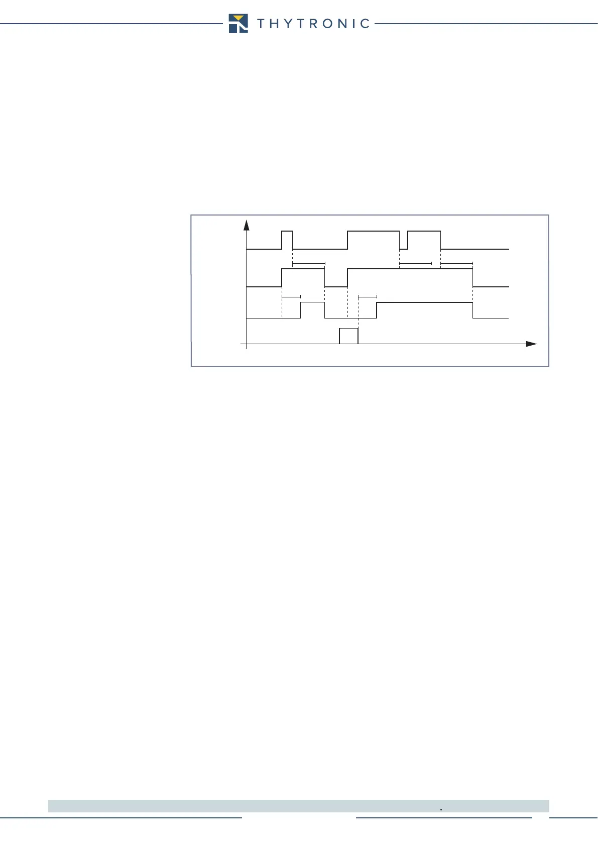
Timers-F50-51.ai
I> Start
I> Trip
t
>
t
>
RESET
INPUT
t
>RES
t
>RES
t
>RES
t
I> element phase overcurrent timers - 50/51