FUNCTION CHARACTERISTICS
73
NA10 - Manual - 04 - 2022
Pulse BLIN1 parameter is available inside the Set \ Pilot wire diagnostic menu; with OFF setting of
the the PulseBLIN1 parameter the pulse control is disabled.
The same setting must be for input and output (PulseBLIN1 and PulseBLOUT1).
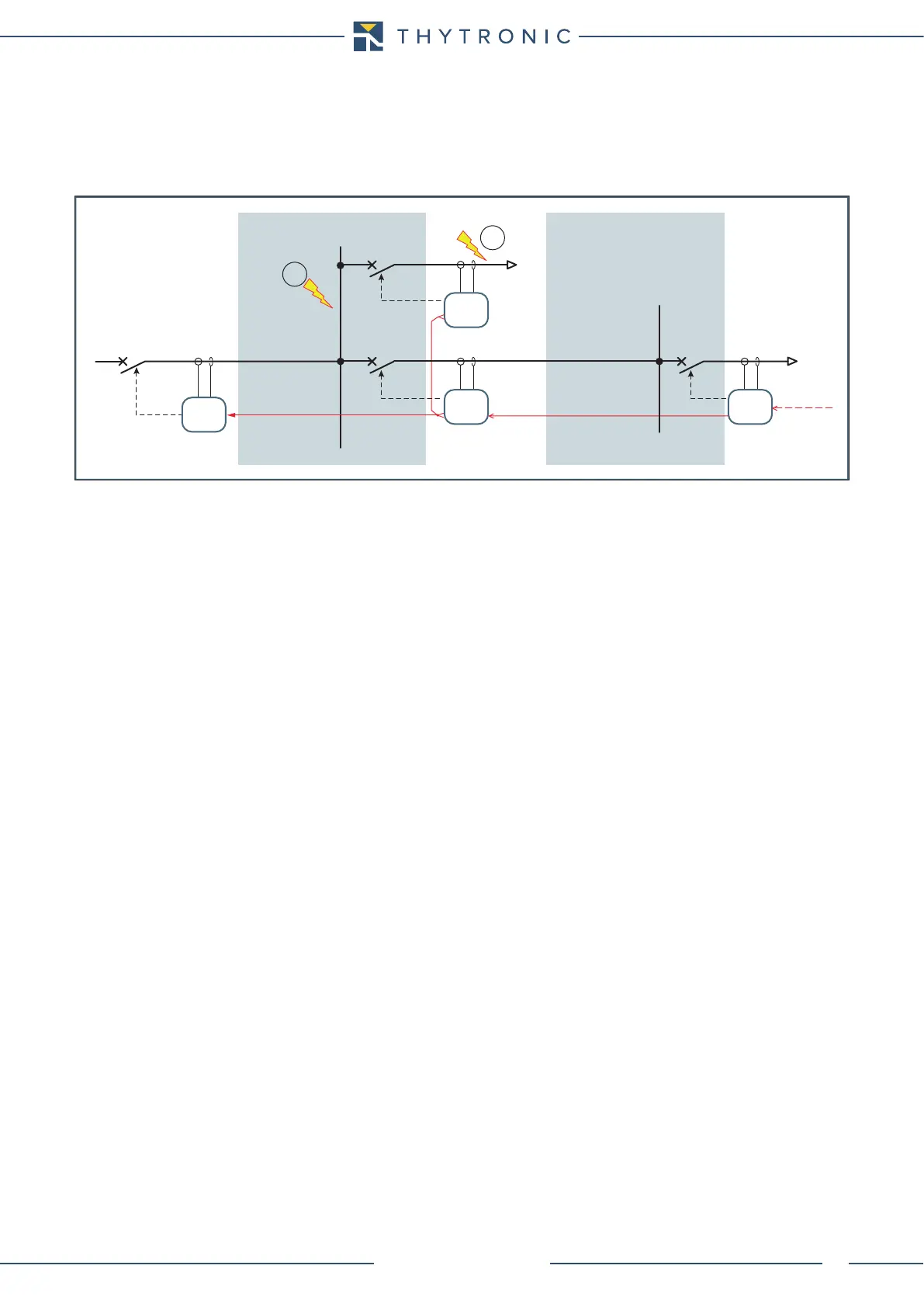
In the following example the output pulses must be enabled inside the device B only (2nd logic se-
lectivity level) and D (1st logic selectivity level).
Setting example
In reference to the above shown schematic diagram, the logic selectivity is performed by means of
the dedicated I/O for the short circuit elements of A, B and C protective relays, so that if a fault arises
in (2), the open order or circuit breaker CB2 is issued and no trip is issued by A device.
A command must be issued for the main circuit breaker CB1 by the A relay with a fault in (1).
A Protection
I>> element with definite time set to 4.5 I
n
with operate time to 0.10 s blocked by start of B and/or C
protection.
Settings:
• I>>
def
= 4.5 I
n
• t>>
def
= 0.100 s
• PulseBLOUT1 = OFF
• PulseBLIN1 = 1 s
• I>>BLK2IN = ON
• I>>BLK2OUT = OFF
• t
B-IPh
= 0.30 s
B Protection
I>> element with definite time set to 4.0 I
n
with operate time to 0.10 s with emission of block output
toward A protection relay.
Settings:
• I>>
def
= 4.0 I
n
• t>>
def
= 0.100 s
• I>>BLK2IN = OFF
• I>>BLK2OUT = ON
• PulseBLIN1 = OFF
• PulseBLOUT1 = 1 s
• t
F-IPh
= 0.25 s
C Protection
I>> element with definite time set to 4.0 I
n
with operate time to 0.10 s with emission of block output
toward A device and block input from D protection relay.
Settings:
• I>>
def
= 4.0 I
n
• t>>
def
= 0.100 s
• I>>BLK2IN = ON
• I>>BLK2OUT = ON
• PulseBLIN1 = 1 s
• PulseBLOUT1 = OFF
• t
F-IPh
= 0.25 s
• t
B-IPh
= 0.30 s
LOAD
Pro_N
Pro_N
Pro_N
CB1
CB2
CB3 CB4
Pro_N
logica_acc-esempio.ai
Logic selectivity
BLIN1
BLOUT1 BLOUT1
BLOUT1
BLIN1
BLIN1
TRIP
TRIP
TRIP
2nd logic selectivity level 1st logic selectivity level
TRIP
1
2
B
C D
A