FUNCTION CHARACTERISTICS
47
NG10 - Manual - 04 - 2022
Similarly the trip of the I
E
>> (I
E
>>) element may be inhibited by start of the third element (I
E
>>>) by
setting ON the Disable IE>> by start IE>>> (IE>>disbyIE>>>) parameter available inside the Set
\ Profile A(or B) side H /L \ Residual overcurrent or high impedance differential restricted earth fault
50N/51N - 87NHIZL \ IE1>>> Element \ Setpoints menu.
All the named parameters can be set separately for Profile A and Profile B (Set \ Profile A(or B).
An adjustable reset time delay is provided for every threshold (t
E
>
RES
, t
E
>>
RES
, t
E
>>>
RES
).
Breaker failure (BF)
Each residual overcurrent element can produce the Breaker Failure output if the IE>BF,IE>>BF
and IE>>>BFinput parameters are set to ON. The parameters are available inside the Set \ Pro-
file A(or B) \ 50N.1/51N - 87NHIZ \ IE> Element (IE>> Element, IE>>> Element) \ Setpoints menus.
[1]
For every of the four thresholds the following block criteria are available.
Logical block (Block1)
If the IE>BLK1,IE>>BLK1and/orIE>>>BLK1input enabling parameters are set to ON and a
binary input is designed for logical block (Block1), the concerning element is blocked off whenever
the given input is active.
[2]
The enabling parameters are available inside the Set \ Profile A(or B) \
50N/51N-87NHIZ \ IE> Element,(IE>> Element, IE>>> Element) \ Definite time (Inverse time) menus,
while the Block1 function must be assigned to the selected binary input inside the Set \ Inputs \
Binary input IN1(x) menus.
Selective block (Block2)
All along the protective elements the selective block may be set.
The logic selectivity function may be performed by means any combination of the following I/O:
• One committed pilot wire input (BLIN1).
• One or more binary inputs designed for input selective block.
• One committed pilot wire output (BLOUT1).
• One or more output relays designed for output selective block.
Only when the committed pilot wire are used the continuity check of the pilot wire link is active.
Use of committed pilot wire input BLIN1:
• The protection is blocked off according the selectivity block criteria when the input BLIN1 is active.
The information about phase or phase+earth block may be select programming the ModeBLIN1
parameter inside the Set \ Profile A(or B) \ Selective block-BLOCK2 \ Selective block IN menus.
Use of binary inputs:
• If the IE>BLK2IN,IE>>BLK2INand/orIE>>>BLK2IN for side 1 a are set to ON and a bi-
nary input is designed for selective block (Block2), the protection is blocked off by phase elements
(Block2 Iph) or by any protection element (Block2 Iph/IE) according the selectivity block criteria.
[3]
The enable IE>BLK2IN,IE>>BLK2INand/orIE>>>BLK2INparametersare available in-
side the Set \ Profile A(or B) \ 50N/51N-87NHIZ \ IE> Element (IE>> Element, IE>>> Element) \ Set-
points menus f, while the Block2 Iph and Block2 Iph/IE functions must be assigned to the
selected binary inputs inside the Set \ Inputs \ Binary input IN1(x) menus (IN1 or INx matching).
Use of committed pilot wire output BLOUT1:
• The information about phase or phase+earth block may be select programming the ModeBLOUT1
parameter (OFF-ONIPh-ONIPh/IE-ONIE) inside Set \ Profile A(or B) \ Selective block-
BLOCK2 \ Selective block OUT menu.
Use of output relay (K1...K6):
• If the IE>BLK2OUT,IE>>BLK2OUTand/orIE>>>BLK2OUT parameters are set to ON and a
output relay is designed for selective block (Block2), the protection issues a block output by phase
elements (BLK2OUT-Iph) or by any protection element (BLK2OUT-Iph/IE), whenever the given ele-
Note 1 The common settings concerning the Breaker failure protection are adjustable inside the Breaker Failure - BF menu.
Note 2 The exhaustive treatment of the logical block (Block 1) function may be found in the “Logic Block” paragraph inside CONTROL AND MONITOR-
ING section
Note 3 The exhaustive treatment of the selective block (Block 2) function may be found in the “Selective Block” paragraph inside CONTROL AND MON-
ITORING section
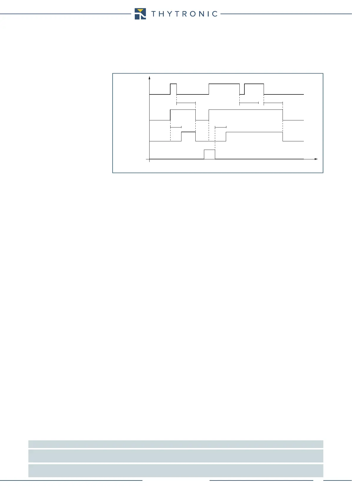
IE> Start
IE> Trip
t
E>
t
E>
RESET
INPUT
t
E>RES
t
E>RES
t
E>RES
t
IE> element residual overcurrent (50N/51N-87NHIZ) - Timers