FUNCTION CHARACTERISTICS
76
NG10 - Manual - 04 - 2022
To enable the selectivity logic input for a generic xx element, the xxBLK2INparameters must be set
to ON inside the Set \ Profile A(or B) \ xxx \ xxx \ Setpoints menus concerning all element where the
selective block is available, xxBLK2INeg I(H)> for side H:
IE>BLK2INinside the Set \ Profile A(or B) \ Residual overcurrent-50/51 \ IE> Element \ Setpoints
menu.
Output selective block
Use of output relays
If the xxBLK2OUT, xxBLK2OUT and/or xxBLK2OUT enable parameters are set to ON and a
output relay is designed for selective block (Block2), the protection issues a block output by phase
elements (BLK2OUT-Iph), by ground elements (BLK2OUT-IE) or by any protection element (BLK2OUT-
Iph/IE), whenever the given start is active.
The BLK2OUT-Iph-K,BLK2OUT-Iph/IE-Kand/or BLK2OUT-IE-Koutput relays must be set in-
side the Set \ Profile A(or B) \ Selective block-BLOCK2 \ Selective block OUT menu; the same for ad-
dressing the LED indicators (BLK2OUT2-Iph-L,BLK2OUT2-IE-LandBLK2OUT2-Iph/IE_L).
When output relays are programmed for selective block output, the t
TR
time delays must reset to
zero; the operation mode must be set with self reset (No-latched inside Set \ Relays submenu) and
the Logic parameters (Energized/De-energized) must be programmed in the same way of the
related binary input connected with-it.
Use of committed pilot wire output BLOUT1
The output is a dry static relay.
The information about phase (ON IPh), earth (ONIE), or phase+earth (ONIPh/IE) concerning the
sending block out signal may be select by means of the ModeBLOUT1 parameter inside the Set \
Profile A(or B) \ Profile A(or B) sides H/L /Selective block-BLOCK2 \ Selective block OUT menu.
The parameters can be set separately for A and B profiles.
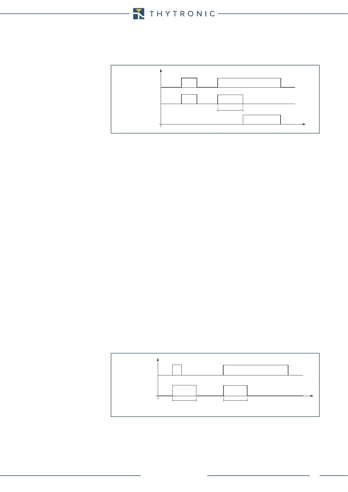
Operation
The selective block outputs go ON at the same time of the xx element start; they hold steady (even
if the start reset to zero) for along the t
F-IPh
, t
F-IE
and
t
F-IPh/IE
adjustable times for phase, earth and
phase+earth functions.
The timers starts when one or more selective block function goes ON; when a timer expires, the
selective block outputs are disregarded (even if the start holds steady).
The t
F-IPh
and t
F-IE
counters start when the output selective block becomes active. When the coun-
ters expire the block selective output is forced off (despite the start xxx remain active).
If the t
F-IPh
, t
F-IE
e
t
F-IPh/IE
timers are cleared the selective block output state is freeze up to the start
xxx remain active.
With a setting other than 0.00 s, the t
F-IPh
, t
F-IE
e
t
F-IPh/IE
timers may be used to provide a backup
protection against breaker failure inside a selectivity logic system, as well as to hold blocked up-
stream protective relays up after the fault is cleared with CB opening to provide solution against
unwanted trips because of a larger reset time compared with the downstream relay (the selectivity
will be lost.
With traditional selective logic systems, in the absence of suitable cares, the event of a circuit
breaker failure causes the block of the receiving relays situated upstream the circuit breaker, so the
fault cannot be cleared.
When using the Pro-N devices inside the selective logic systems, the answer to the circuit breaker
failure problem can be solved by means of, (as well as the BF-Breaker Failure element) or by means
of a threshold adjusted for time selectivity, through use of the output block reset timer too with the
intent that avoid permanently block of all upstream relays by downstream block signals (the only one
unblocked relays deals to the fault breaker).
TB-timer.ai
t
t
B-Iph
/t
B-IE
BLIN2IN-Iph/BLIN2IN-IE
tB timeout
INPUT BLOCK
(binary input and/or BLIN1)
tB timer
TF-timer.ai
t
t
F-IPh,
t
F-IE,
t
F-IPh/IE
t
F-IPh,
t
F-IE,
t
F-IPh/IE
Start xx
(protezioni interne)
BLK2OUT-Iph
BLK2OUT-IE
BLK2OUT-Iph/IE
tF timer (Block2)