FUNCTION CHARACTERISTICS
77
NG10 - Manual - 04 - 2022
The t
F-IPh
, t
F-IE,
t
F-IPh/IE
timers must be adjusted according the following rule (Ejemplo for t
F-Iph
):
t
F-Iph
= t + T
AP
+ t
rip
+ e
t
+ e
s
where t is the larger phase protection operate time, T
AP
is the circuit breaker operate time (with arc
extinction), t
rip
is the larger reset time of all protective relays inside the selective logic system, e
t
is
an potential selectivity margin relative to the t
F-x
time of the downstream relays, e
s
is a safety margin
need to include timers errors (tolerances).
Diagnostic
To guarantee maximum fail-safety, the relay performs a run time monitoring for pilot wire continuity
and pilot wire shorting.
[1]
Exactly the output blocking circuit periodically produces a pulse, having a small enough width in
order to be ignored as an effective blocking signal by the input blocking circuit of the upstream
protection, but suitable to prove the continuity of the pilot wire.
Furthermore a permanent activation (or better, with a duration longer than a preset time) of the
blocking signal is identified, as a warning for a possible short circuit in the pilot wire or in the output
circuit of the downstream protection.
The periodic pulses that are sent by output circuit may be enabled or disabled by means the Pulse-
BLOUT1 parameter available inside the Set \ Pilot wire diagnostic menu; with OFF setting the
pulses are disabled.
[2]
If no pulses are received inside an adjustable time window at the selective block input circuit, a
break pilot wire alarm is issued; the information is available for reading (Breaked BLIN1 data inside
Read \ Pilot wire diagnostic submenu) and can drive an output relay and or a LED (PulseBLIN-K
and or a PulseBLIN-L parameters inside Set \ Pilot wire diagnostic submenu).
Note 1 Full diagnostic of pilot wires is only available when committed pilot wire input/outputs are employed
Note 2 When several outputs are parallel linked the pulse emission must be enabled inside one device only, sooner inside the outermost device
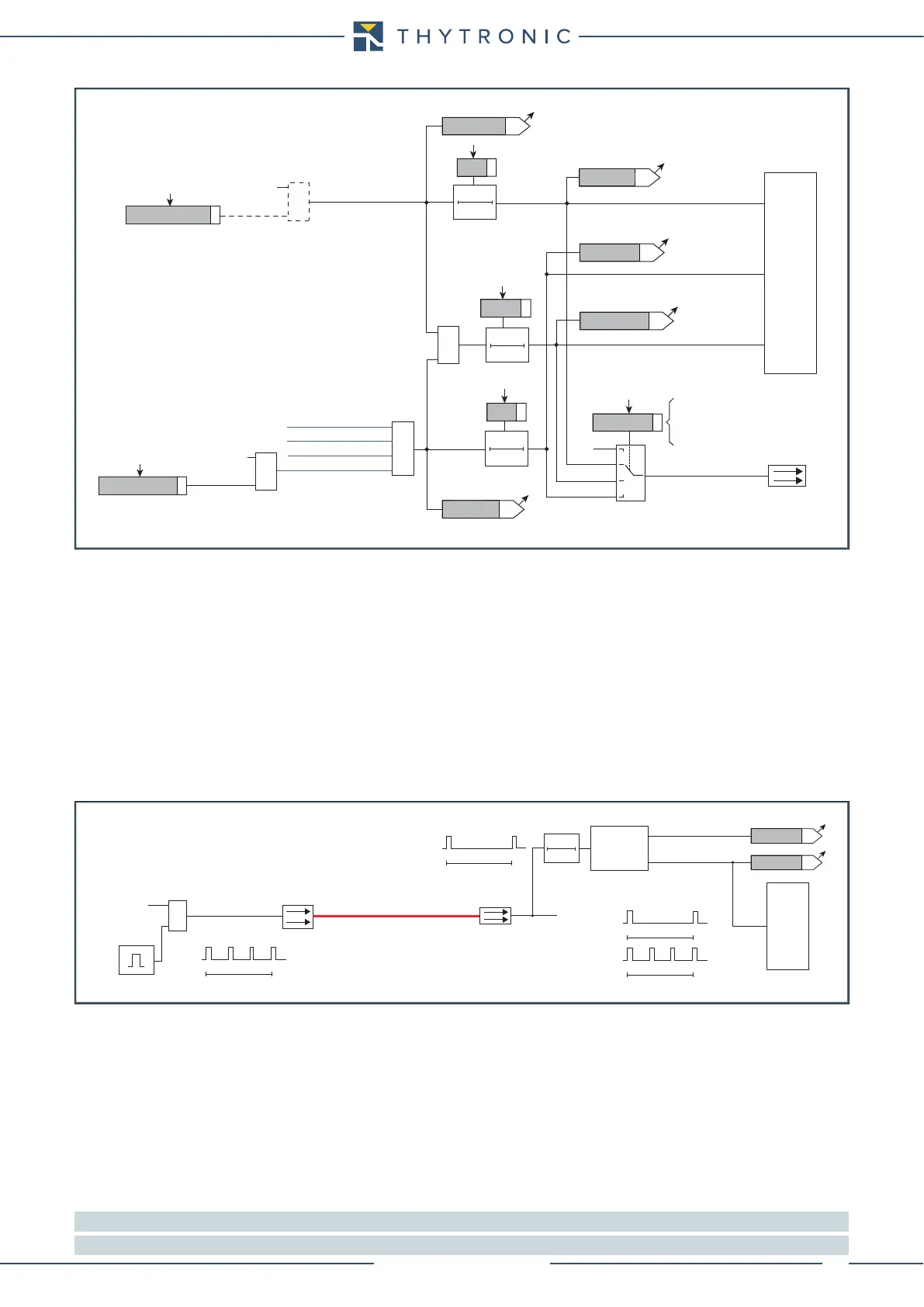
Pilot wire output
Pilot wire link
≥ 1
Pulse
generator
BLOCK OUT
BLOCK IN
T 0
Pilot wire
Diagnostic
Pilot wire input
No pulses
Permanently “ON”
BLIN1
BLOUT1
Breaked BLIN
TRIPPING MATRIX
(LED+RELAYS)
Shorted BLIN
Pulse BLIN1
Pulse BLIN1
Pulse BLOUT1
Pulse BLOUT1
Block2-diagram.ai
&
Start 64REF>
&
Block2 output
(ON≡ Enable)
64REF>BLK2OUT
Pilot wire output
BLOUT1
TRIPPING MATRIX (LED+RELAYS)
ModeBLOUT1
A
B
C
D
≥ 1
ST-Iph BLK2
ST-IE BLK2
BLK2OUT-Iph
BLK2OUT-Iph/IE
BLK2OUT-IE
A = OFF
B = ON IPh
C = ON IPh/IE
D = ON IE
BLK2OUT-IPh-K
BLK2OUT-IPh-L
BLK2OUT-IPh/IE-K
BLK2OUT-IPh/IE-L
BLK2OUT-IE-K
BLK2OUT-IE-L
87G-M-L Block2 OUT
≥ 1
Start 87G-M-L
Block2 output
(ON≡ Enable)
87G-M-LBLK2OUT
I
E
>> Block2 OUT
I
E
>>> Block2 OUT
64REF> Block2 OUT
I
E
> Block2 OUT
Logic diagram concerning the selective block output - Block2 output
t
F-IPh
t
F-IPh/IE
t
F-IE
T0
t
F-IPh/IE
T0
t
F-IPh
T0
t
F-IE