SSG000\08
12-2005
74
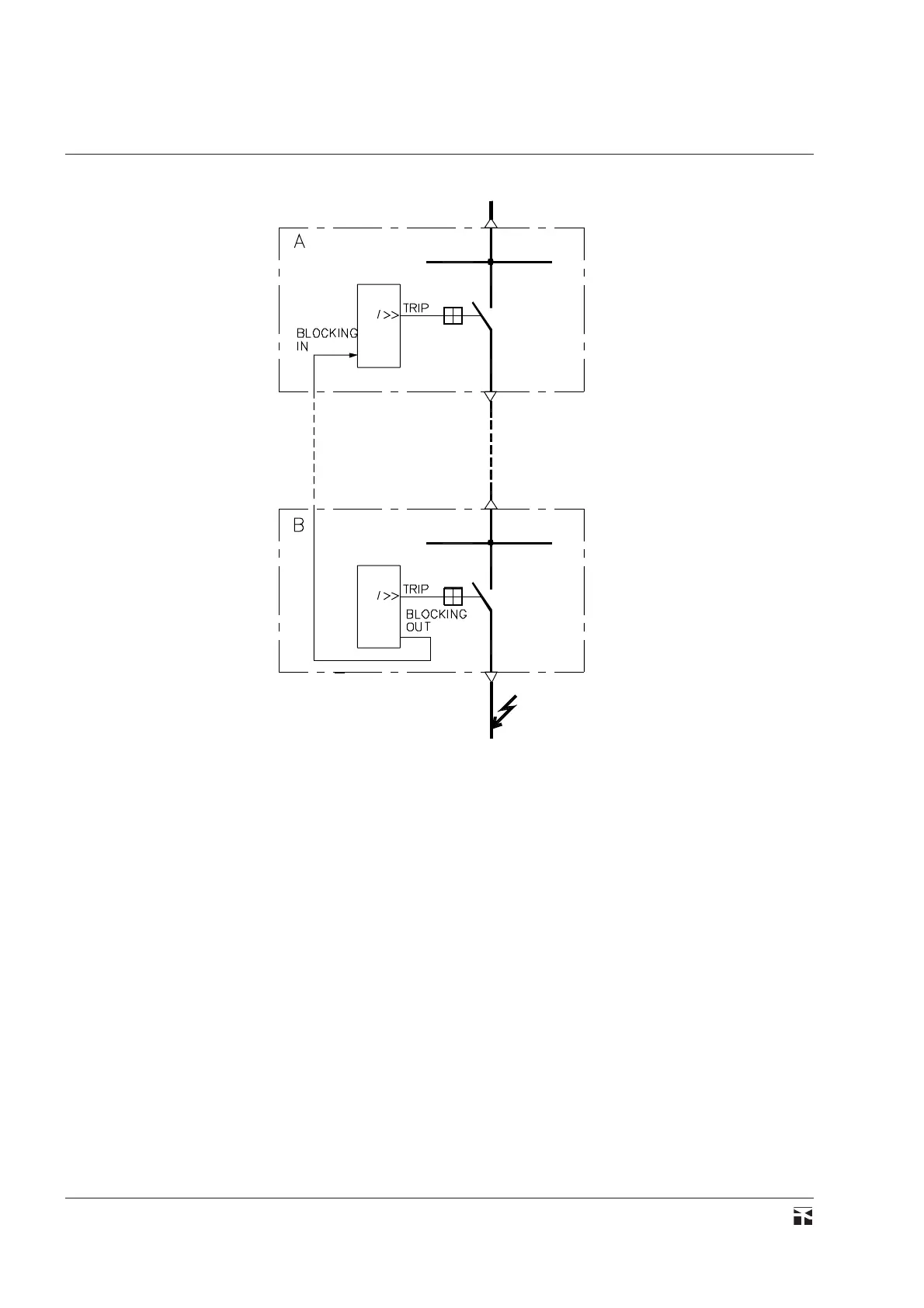
Fig. 38 - Schema di principio di un sistema di blocco a logica
accelerata tra due protezioni A e B.
L'assegnazione delle tarature avviene in maniera simile a
quanto indicato sopra per le altre funzioni di protezione; occorre
entrare nel sottomenù 50-51,BANK A, modificare le tarature
secondo i valori desiderati e attivare la funzione di blocco in
ingresso e in uscita.
Ad esempio le tarature delle protezioni A e B possono essere
impostate come segue:
- protezione A
I>> 4.5 In
t>> 0.20 s
BLK IN t>> ON
BLK OUT t>> OFF
t>>b 0.05 s
- protezione B
I>> 4.0 In
t>> 0.05 s
BLK IN t>> OFF
BLK OUT t>> ON
Il tempo t>>b rappresenta il tempo d'intervento della prote-
zione a monte A alla scomparsa del segnale di blocco proveniente
Fig. 38 - Principle diagram of an accelerated logic blocking
system for protections A and B.
The assignment of the setting values is carried out in the same
way as above indicated for the other protection functions; the
submenu 50-51,BANK A must be entered to modify the setting
values and to enable the input and output blocking functions.
As an example protections A and B can be preset as follows:
- protection A
I>> 4.5 In
t>> 0.20 s
BLK IN t>> ON
BLK OUT t>> OFF
t>>b 0.05 s
- protection B
I>> 4.0 In
t>> 0.05 s
BLK IN t>> OFF
BLK OUT t>> ON
The time t>>b represents the operation time of the upstream
protection A, when disappearing the blocking signal issued from