SSG
87
SSG000\08
12-2005
Fig. 43
- azzerare inizialmente la corrente;
- applicare istantaneamente una corrente pari a 2.5 volte il
valore della soglia e avente lo sfasamento per la massima
sensibilità, e verificare che il tempo d’intervento corrisponda al
valore impostato;
- azzerare istantaneamente la corrente e rilevare il tempo di
ripristino della protezione.
2 - Funzione predisposta con tempo dipendente
Le procedure di prova per la verifica della soglia d'intervento
e per la verifica del settore di sfasamento d'intervento sono le
stesse indicate sopra per le funzioni a tempo indipendente;
occorre tenere presente che la soglia d'intervento
I
θT
è pari al
110% del valore di riferimento
I
θS
per cui i valori di corrente ivi
indicati sono relativi a 1.1 ×
I
θS
.
La procedura di prova per la verifica del tempo d'intervento è
la seguente:
- azzerare inizialmente la corrente;
- applicare istantaneamente una corrente pari a 4 volte il
valore di riferimento
I
θS
e avente lo sfasa-mento per la massima
sensibilità, e verificare che il tempo d’intervento corrisponda al
valore impostato;
- azzerare istantaneamente la corrente e rilevare il tempo di
ripristino della protezione.
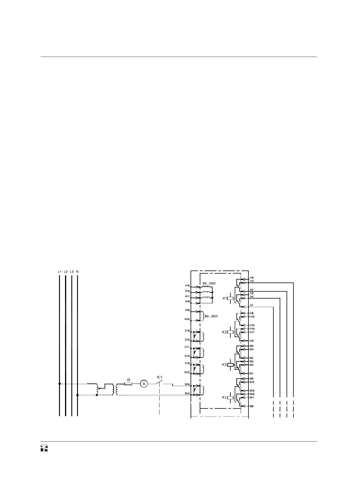
Verifica protezione di massima corrente residua
(50N-51N)
Questa prova può essere eseguita mediante lo schema ripor-
tato in fig. 43 .
La prova consiste nella verifica della soglia e del tempo
d'intervento. Valgono le stesse considerazioni esposte sopra
relativamente alla funzione di massima corrente di fase (50-51).
- initially set the current at zero;
- apply instantaneously a current value equal to 2.5 times the
value of the trip threshold and having a phase shift for maximum
sensitivity, and ascertain that the trip time corresponds to the
preset value;
- set instantaneously the current at zero and detect the reset time
of the protection.
2 - Function with dependent time setting
The testing procedures for the checking of the operation
threshold and the operation phase difference sector are the same
as above indicated for independent time functions; it must be
pointed out that the operation threshold
I
θT
is equal to 110% of the
reference value
I
θS
: then the above values must be referred to 1.1
×
I
θS
.
The test procedure for checking the trip time is as follows:
- initially set the current at zero;
- apply instantaneously a current value equal to 4 times the
reference value
I
qS
and having a phase shift for the maximum relay
sensitivity, and observe that the trip time corresponds to the preset
value;
- set instantaneously the current at zero and detect the reset
time of the protection.
Checking the residual overcurrent function (50N-
51N)
This test can be carried out by using a connection scheme as
shown in fig. 43 .
The test comprises the checking of the operation threshold and
time. The same instructions apply, which are indicated above for
the overcurrent function (50-51).