Pag. 3 / 8 0CAR6IN016500
for Solar Panels with forced circulation
K1 K2 K3 K4
TMAX
MENU
OFF
INTEG.
T
P1
P2
TEMP TEST SET
1 2 3 4 5 6 7 8 9 10 11 12
13 14 15 16
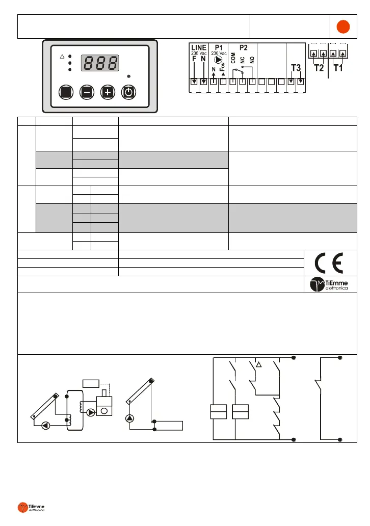
Fig. 1: Exterior Aspect and electrical connections
Temperature Max: 200°C
Measurement Range: 0÷190°C
Temperature Range: 0÷99°C
Measurement Range: 0÷99°C
Inbox Controller 3 modules: 120 x 80 x 50 mm
EN 60730-1 50081-1 EN 60730-1 A1 50081-2
TiEmme elettronica Marsciano (PG) Italia
Tel: +39 075.8743.905 Fax: +39 075.8742239 info@tiemmeelettronica.it
Mounting and Installation must be carried out by trained personnel in compliance with current safety
and electrical standards.
Place the device in a dry place away from any source of heat
Make sure to position the Probes properly in order to obtain correct temperature readings
Keep sensor and power cables separate. Use free-braided bipolar screened cable min. cross-
section 1.5 mm² and max. Length 25 m.
The connection to the main power must be carried out only after completing the installation
P1
T1ice
T3-max
T3Sic
T2Sic
T1Sic
ICE
T
P2
INTEG.
A31
A26
A02
A17
A27
A03
P06
t05
t06
t07
t08
A25
T1
P1
P2
T2
T3
P3
Piscina
Pool
P1
T2
T3
T1
T1Pro
A04
Fig. 2 Diagrams of Operation
 Loading...