19 20
21 20
29
28
31
37
63
6
63 3137 29 282829373163
6
6
26a
26d
26c
4c
4b
4c
4b
4c
4b
40
5
9
34
1b
2
39
3
8a
25
3a
38
37
36
30
55
30
7
51
50a
10
49
4
17
49
33
4a
47a
33b
49
33b
24
5a
14
65
1a
8
23
46
Coupling
guard-left
Coupling
guard-right
Screw, washer
Pump head
Lining
Diffuser
Support diffuser
Neck ring cover
Neck ring
Coupling
Inducer
Baseplate
Shaft pin
Nut M16
Washer 16
Screw
Circlip cover
strap
Impeller sleeve
Flange
Retaining ring
Nut M10-LH
Impeller washer
Staybolt
Inlet&outlet
chamber-Flange type
Inlet&outlet
chamber-cutting ferrule type
Inlet&outlet
chamber-pipe thread type
Drain screw
1a.
1b.
2.
3.
3a.
4.
4a.
4b.
4c.
5.
5a.
6.
7.
8.
8a.
9.
10.
14.
17.
20.
21.
23.
24.
25.
26a.
26c.
26d.
28.
Drain plug
O ring 169×3.3
Y ring
Sleeve for support diffuser
Long sleeve for support diffuser
Mechanical seal
Air vent plug
O ring 16×2.8
Air vent screw
Bolt、washer
Motor
Adjusting rubber
Bearing
Impeller
Top diffuser
Shaft
Cylinder
O ring retainer
Screw M8× 20、
Washer 8
29.
30.
31.
33.
33b.
34.
36.
37.
38.
39.
40.
46.
47a.
49.
50a.
51.
55.
63.
65.
28293731
63
26g
4c
4b
4c
4b
4c
4b
40
5
9
34
1b
2
39
3
8a
25
38
37
36
30
55
30
14
65
1a
8
7
51
50a
10
49
4
17
49
33
4a
47a
33b
49
33b
46
24
5a
23
Coupling guard-left
Coupling guard-right
Screw, washer
Pump head
Diffuser
Support diffuser
Neck ring cover
Neck ring
Coupling
Inducer
Shaft pin
Nut M16
Washer 16
Screw
Circlip cover
strap
Impeller sleeve
Nut M10-LH
Impeller washer
Staybolt
Inlet&outlet chamber-Flange type
Drain screw
Drain plug
O ring 169×3.3
1a.
1b.
2.
3.
4.
4a.
4b.
4c.
5.
5a.
7.
8.
8a.
9.
10.
14.
17.
23.
24.
25.
26g.
28.
29.
30.
Y ring
Sleeve for support diffuser
Long sleeve for support diffuser
Mechanical seal
Air vent plug
O ring 16×2.8
Air vent screw
Bolt、washer
Motor
Adjusting rubber
Bearing
Impeller
Top diffuser
Shaft
Cylinder
O ring retainer
Screw M8×20、Washer 8
31.
33.
33b.
34.
36.
37.
38.
39.
40.
46.
47a.
49.
50a.
51.
55.
63.
65.
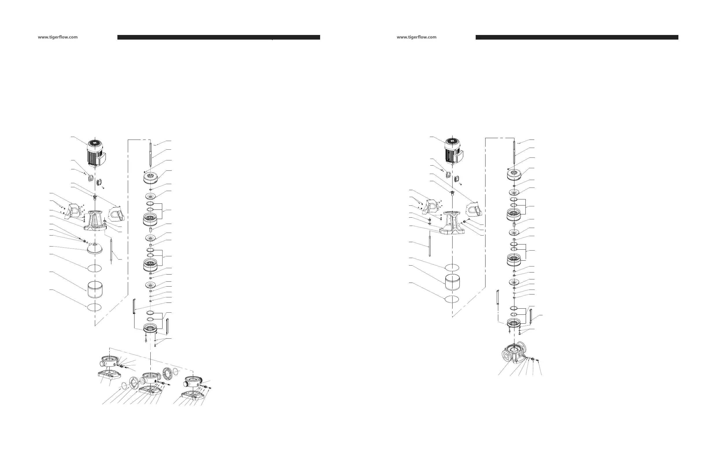
4.1. Structure
Drawing 1-G CDF15, 20
4.1. Structure
Drawing 1-H CD15, 20
4. INSTALLATION
Installation, Operation and Maintenance Manual Installation, Operation and Maintenance Manual