13 14
4.1. Structure
40
5
9
34
1a
2
39
8
3
25
38
36
37
3a
60
30
50a
7
51
10
49
47
5a
47
49
33
4a
47a
22
49
47
23
55
30
4
4c
4b
4c
4b
1b
24
8a
4c
4b
64 65
66
29
37
63
31
26f
6a
28
2937
63
6a
26c
63
31
37
29
21
28
626a20
28
29
373163
31
26d
6a 28
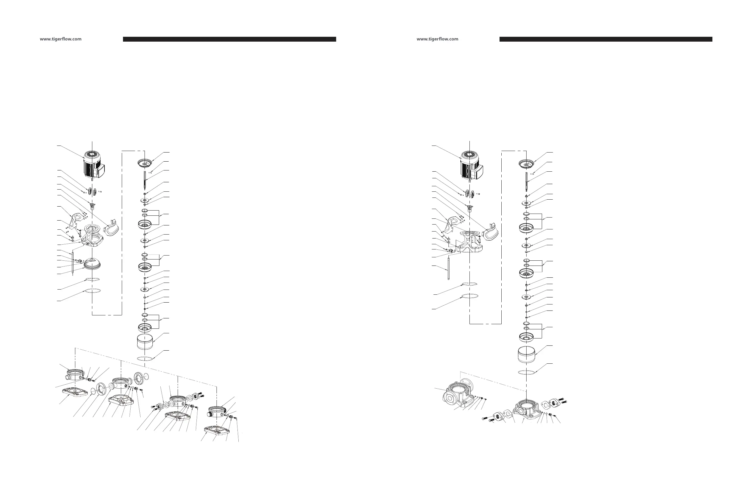
Drawing 1-A CDF3
Coupling guard-left
Coupling guard-right
Screw, washer
Pump head
Lining
Diffuser
Support diffuser
Neck ring cover
Neck ring
Coupling
Inducer
Baseplate-Flange type
Baseplate-cutting ferrule type
Shaft pin
Nut M12
Washer 12
Screw
Circlip cover
Flange
Retaining ring
Supporting washer
Nut M8-LH
Impeller washer
Staybolt
Inlet&outlet chamber-Flange type
Inlet&outlet chamber-cutting ferrule type
Inlet&outlet chamber-pipe thread type
Inlet&outlet chamber-oval flange type
1a.
1b.
2.
3.
3a.
4.
4a.
4b.
4c.
5.
5a.
6.
6a.
7.
8.
8a.
9.
10.
20.
21.
22.
23.
24.
25.
26a.
26c.
26d.
26f.
Drain screw M10
Drain plug
O ring 136.5×3.3
Y ring
Sleeve for support diffuser
Mechanical seal
Air vent plug
O ring 16×2.8
Air vent screw
Bolt, washer
Motor
Impeller sleeve 9.6×12.6
Bearing
Impeller
Top diffuser
Shaft
Cylinder
Corrugated spring
O ring retainer
Bolt M10×40
Oval flange
Oval flange gasket
28.
29.
30.
31.
33.
34.
36.
37.
38.
39.
40.
47.
47a.
49.
50a.
51.
55.
60.
63.
64.
65.
66.
4.1. Structure
40
5
9
34
1a
2
39
8
3
25
38
36
37
60
30
1b
8a
50a
7
51
10
49
47
5a
47
49
33
4a
47a
22
49
47
23
55
30
4
4c
4b
4c
4b
24
4c
4b
64
66
65
37
63
28
29
26g
28
29
37
31
63
31
26e
Drawing 1-B CD3
Coupling guard-left
Coupling guard-right
Screw, washer
Pump head
Diffuser
Support diffuser
Neck ring cover
Neck ring
Coupling
Inducer
Shaft pin
Nut M12
Washer 12
Screw
Circlip cover
Supporting washer
Nut M8-LH
Impeller washer
Staybolt
Inlet&outlet chamber-Flange type
Inlet&outlet chamber-oval flange type
Drain screw M10
Drain plug
O ring 136.5×3.3
Y ring
1a.
1b.
2.
3.
4.
4a.
4b.
4c.
5.
5a.
7.
8.
8a.
9.
10.
22.
23.
24.
25.
26g.
26e.
28.
29.
30.
31.
Sleeve for support diffuser
Mechanical seal
Air vent plug
O ring 16×2.8
Air vent screw
Bolt, washer
Motor
Impeller sleeve 9.6×12.6
Bearing
Impeller
Top diffuser
Shaft
Cylinder
Corrugated spring
O ring retainer
Bolt M10×40
Oval flange
Oval flange gasket
33.
34.
36.
37.
38.
39.
40.
47.
47.
49.
50a.
51.
55.
60.
63.
64.
65.
66.
Installation, Operation and Maintenance Manual Installation, Operation and Maintenance Manual
4. INSTALLATION
 Loading...