Do you have a question about the Tigo TS4-A-O and is the answer not in the manual?
Explains the role of CCA and TAP in system communication.
Details on how to mount TS4 units using clips or bolts.
Guidance on TAP placement within the array and its connections.
Explains the meaning of different LED lights on the CCA.
Table listing power, voltage, and current ratings for TS4 models.
Information on the PVRSS certification and installation requirements.
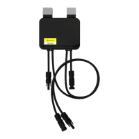
How to connect the CCA to TAPs and power sources.
The Tigo TS4-A-O/S/M with TAP and CCA is a comprehensive solution designed to optimize and manage solar PV systems, providing module-level power electronics (MLPE) for enhanced performance, safety, and monitoring. This system is particularly focused on ensuring compliance with rapid shutdown requirements, a critical safety feature for PV installations.
The core function of the Tigo system is to provide module-level optimization, monitoring, and rapid shutdown capabilities for solar PV arrays. It consists of three primary components:
Together, these components create a robust ecosystem that allows for granular control and visibility into the PV system's performance. The system ensures that in the event of an AC power loss (e.g., inverter shutdown or utility grid disconnection), the TS4s rapidly de-energize the PV modules, bringing the array to a safe voltage level as required by electrical codes.
The Tigo system is designed for ease of installation and operation, offering several features that enhance its usability:
Maintaining the Tigo system is straightforward, with features designed to ensure long-term reliability and ease of service:
| Maximum Input Voltage | 60 V |
|---|---|
| Maximum Output Current | 15 A |
| Operating Temperature Range | -40°C to +85°C |
| Maximum Input Current | 15 A |
| Maximum Output Voltage | 80 V |
| IP Rating | IP68 |
| Efficiency | 99.5% |
| Function | Optimization |
| Protection Features | Over-temperature, over-voltage |
| Type | MLPE (Module Level Power Electronics) |