7
PRELIMINARY
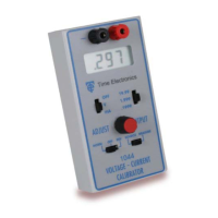
Operation of the 1044 can be defined as four different procedures; volt-
age source, current source, voltage measure and current measure.
For correct operation ensure that the battery low indicator is not showing
in the display. The output will only be indicated when the polarity switch is
in either ‘normal’ or ‘reverse’ positions, not in the ‘off’ position. Be certain
to check the polarity settings before connecting the unit under test. The
display will show a negative sign ‘-’ if the output is in reverse polarity
mode.
The display will show the actual applied output in source mode so if the
value alters when the unit under test is connected, the loading specifica-
tions might be exceeded. This is also useful because it eliminates poten-
tial errors when connecting to an unknown u.u.t.
Always check the mode of operation and range values before connecting
to the unit under test or to the circuit being measured. If the 1044 will not
source or measure the protection fuse has probably blown due to an ex-
cessive current being applied to the unit. This can be found inside the
1044 - refer to the Calibration section for more details.
SETTING A VOLTAGE OUTPUT
To set a voltage output, set the function switch to V and set the appropri-
ate voltage range. Set to the desired voltage by turning the output adjust
multiturn potentiometer, the output voltage shown in the display will alter.
The unit under test may now be connected observing the polarity.