2 Installation
2.1 Location
To receive GPS signals the Time Server's antenna must be located in a location where it can “see” the
sky. The GPS module itself is highly sensitive and able to “see” the GPS satellite signals from within
many structures. Multi-Story or metal structures may block the GPS signals such that the antenna must
be located elsewhere. In these cases, the GPS antenna may be located in a window. The Time Server
box can be located anywhere on the network. All that is required is power and a wired network
connection. In the worst case, an outdoor antenna may be required.
2.2 Connections
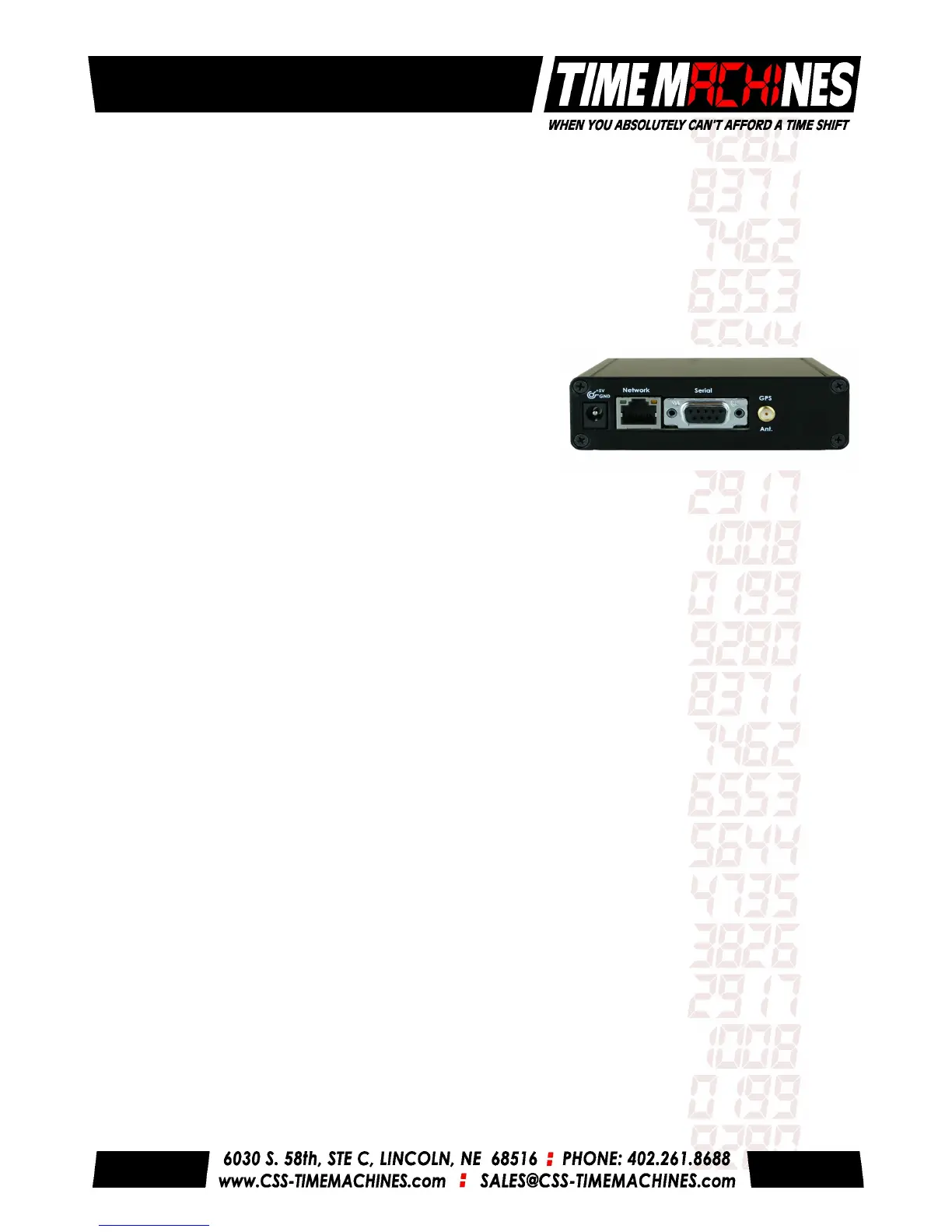
2.2.1 Antenna
The GPS antenna is connected through the circular female SMA connector on the rear of the Time
Server. By default, the GPS antenna connection provides 3.3V to power the LNA in the GPS antenna.
This is correct for the supplied GPS patch antenna with the magnetic base. This voltage can be
changed with a jumper on the inside of the Time Server. The Time Server has to be opened up and a
jumper moved.
Jumper J2 Jumper J8
A: 5.0V B: 3.3V (default) A: Reset to Factory B: Normal Operation
The only time this jumper would changed would be to allow use of a different antenna that requires
+5V for the LNA in the antenna. This might be the case for an outdoor installation.
2.2.2 Power
A +5V power supply is supplied with the unit. Connect one end to a standard United States 110-
120VV outlet and the barrel connector to the rear of the Time Server. The time server will begin trying
to find the GPS satellites. On power-up, synchronization to the GPS satellites will take several
minutes. No battery backup of position is provided to allow for a warm start so the Time Server is
always starting from scratch in determining its location to achieve GPS lock.
2.2.3 Network
Connect the 10/100 RJ45 port on the back of the Time Server to a network connection. Verify that the
network settings are correct for your system. See the configuration section of this manual for more
information on doing this.
2.2.4 Front Panel Indications
The front panel of the Time Server is very basic in its appearance. Three LEDs show the current status
of the unit. The POW indicator indicates that the unit is receiving power through its wall power supply.
The LOCK indication indicates that the GPS has located at least three satellites. The SEC LED will
blink each second showing that the GPS module is now synchronized to the GPS time signals.
Installation and Operations Manual | Page 2
 Loading...